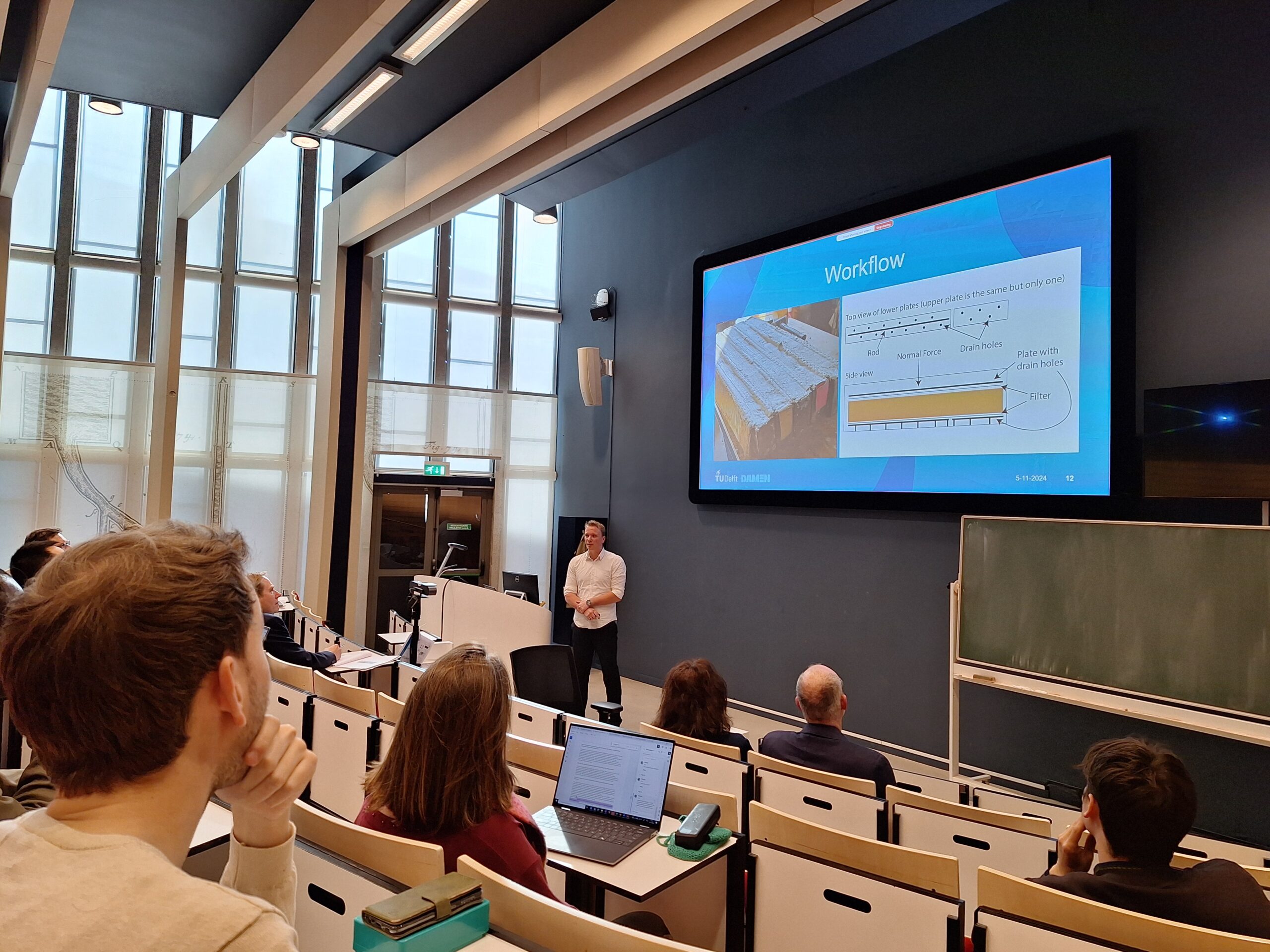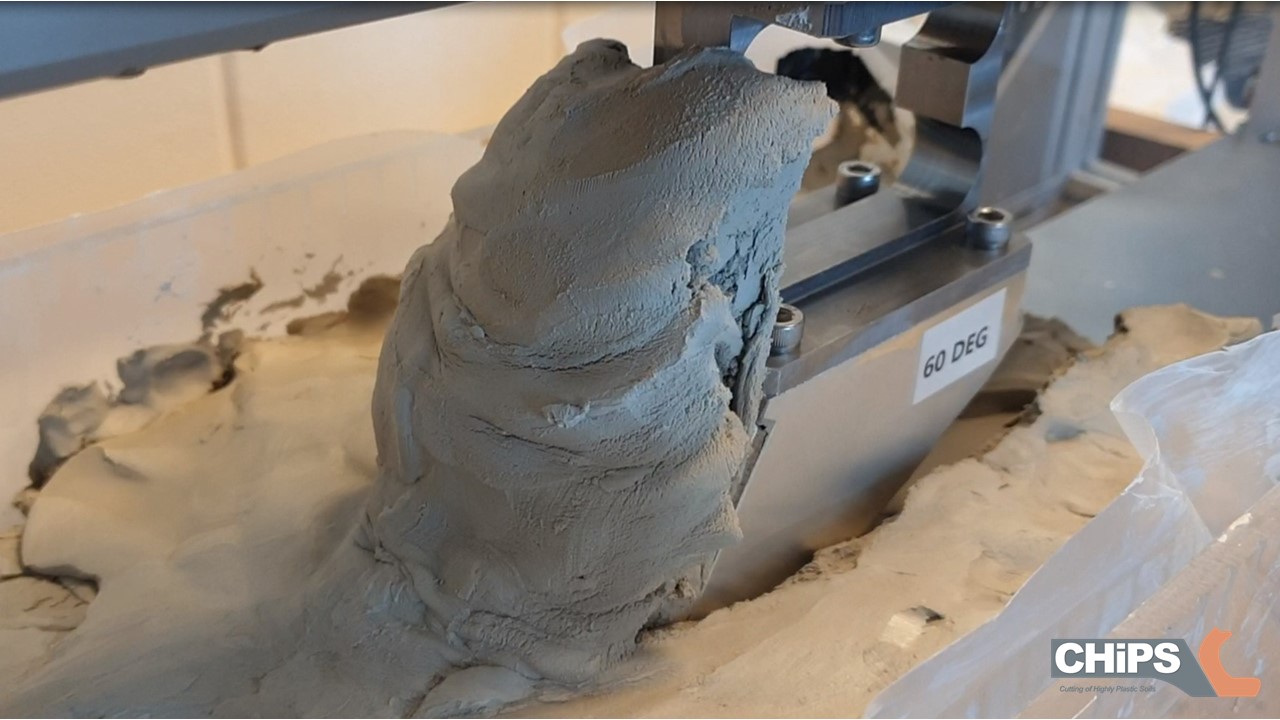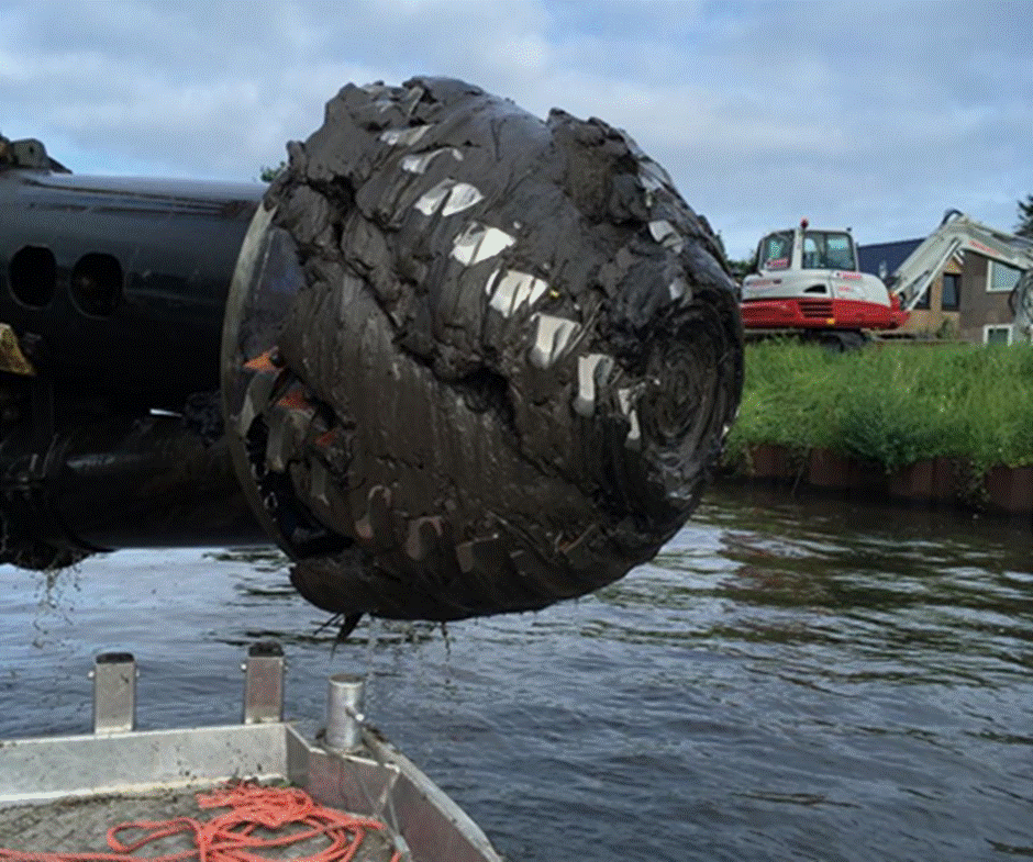
Fully covered cutter head in sticky clayThis week, I will be presenting my paper1 about the initial experiments on the test rig at the 5th International Symposium on Frontiers in Offshore Geotechnics (ISFOG 2025)2. I will be there in the breaks to explain my poster3 in the lunch breaks. For my audience not present at the symposium, I can highlight the most interesting parts here. I presume, most of you are aware of the operation of a Cutter Suction Dredge and also know about its problems when working in clay. The clay will adhere to the teeth and arms and clog the cutter head. This leads to interruption of the project and in consequence: time and cost overruns. Also, the production itself is difficult to calculate. This is why we at Damen Dredging Equipment started the CHiPS project with the TU Delft4 to investigate the process, improve the estimation model and optimise the design of the cutter head for operation in clay.
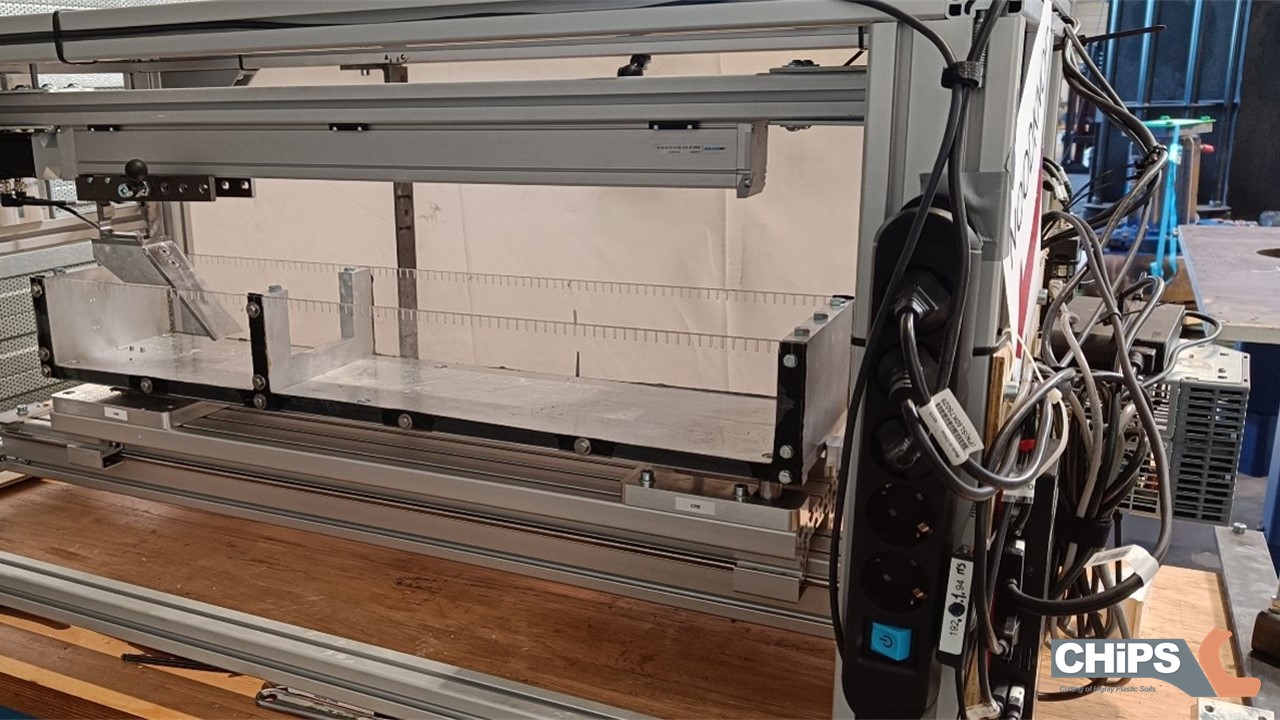
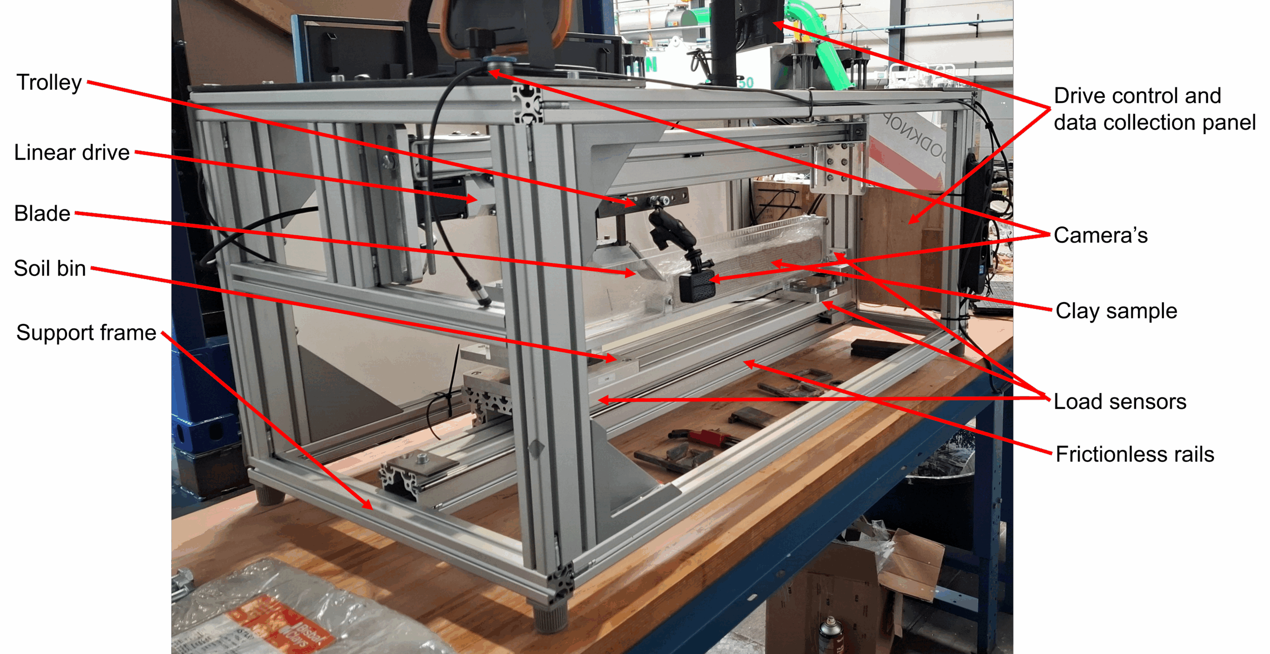
Forces involved in the cutting of clayFor this purpose, we constructed a linear cutting test rig. Last post about the graduation of Fabian Kruis has more on the results of his thesis5. In the ISFOG article, we wrote about the design and performance of the rig and the opportunities it provides for further research. The design criteria for the rig as was laid down in the assignment for Ines Ben M’hamed were6:
- Identifying the main parameters influencing the cutting forces and the cutting regime.
- Designing general arrangement for testing linear cutting models.
- Capture the signals for force and deformation.
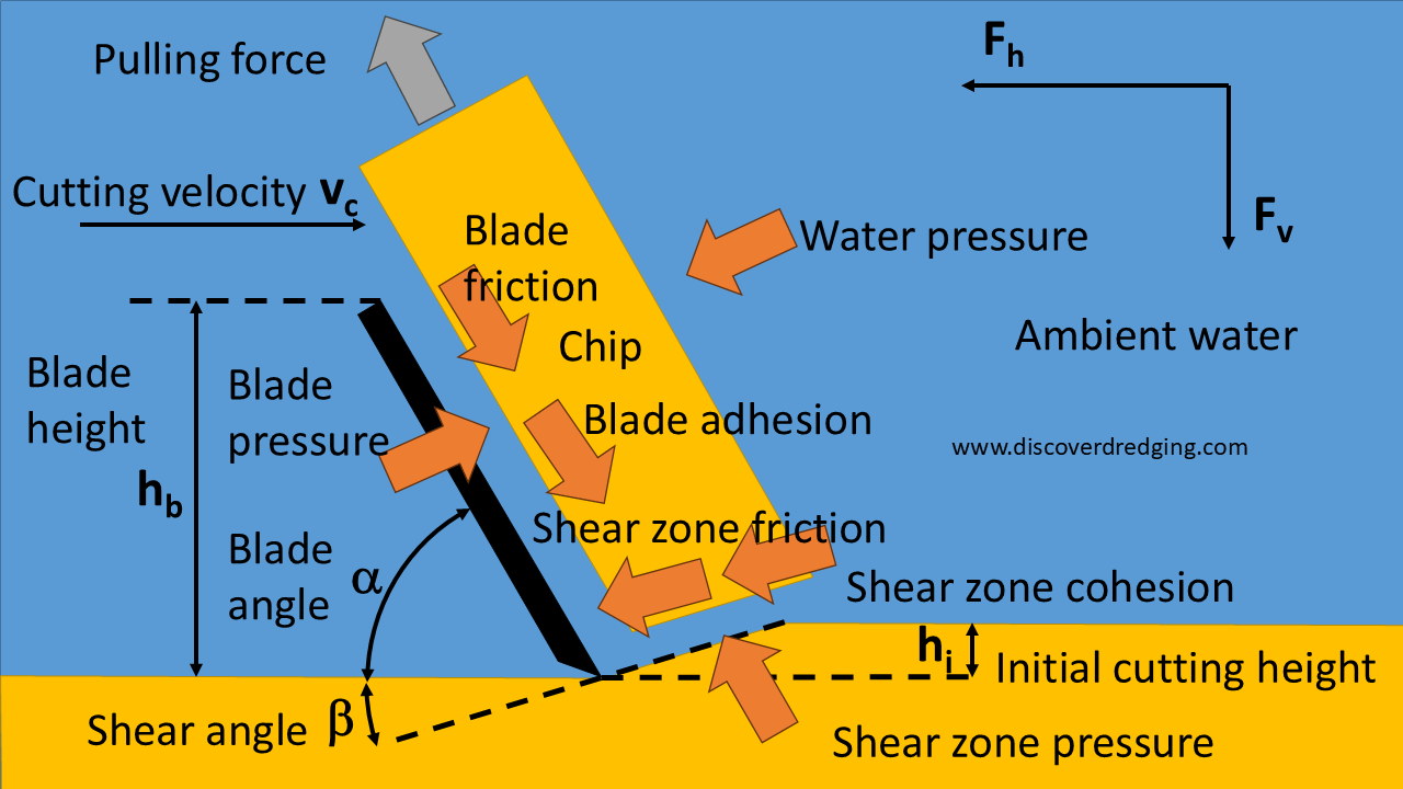
The developed test rig was inspired by the model described by Hatamura and Chijiiwa7. The blade is attached to a linear moving trolley, cutting through a block of clay mounted in a frictionless moving soil bin. The reaction forces on the box are measured. and images of the grid printed on the side of the clay block are captured with a GoPro camera of later evaluation with PIVlab®. A set of 30 experiments was defined according to the Buckingham-PI method as presented at the CEDA Dredging Days last year8.
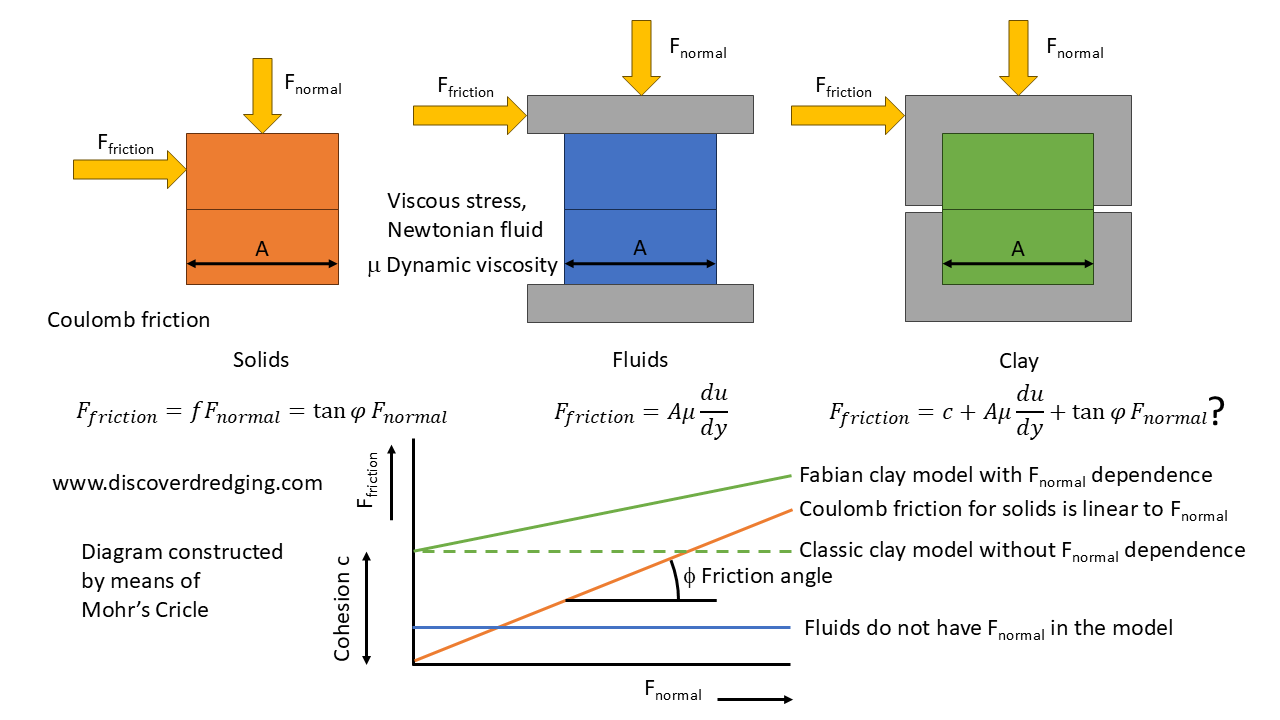
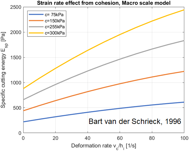
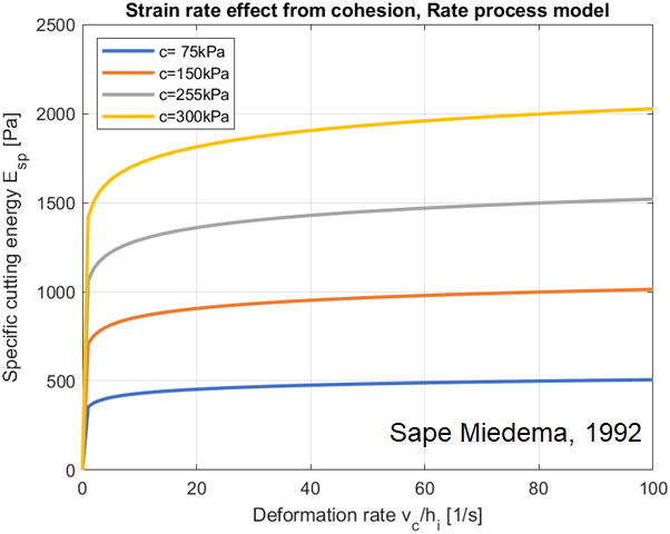
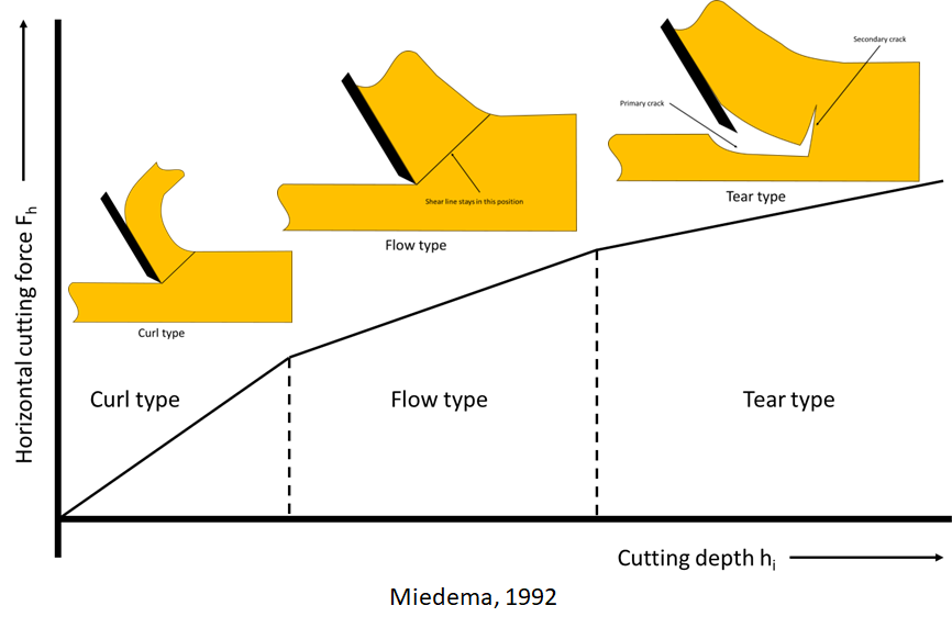
Next to the cohesion and adhesion, the tensile strength of the clay had to be measured to obtain a consistent result. We could confirm the linear relation between cutting depth and the cutting force as predicted by existing models from literature. As we were using modern techniques for capturing images, we were able to accurately measure the displacements with the PIVlab® application. The good results are due to the novel printing technique developed by Fabian Kruis, to apply a grid on the side of the clay sample. One remarkable result is, that most models for the calculation of the sliding forces, only take adhesion into account, but measurements indicate that the external friction cannot be neglected. This appeared in the measured shear angle, which was much lower than the shear angle predicted by existing models.
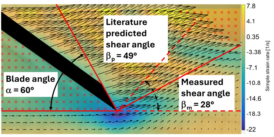 Captured deformations in a vector field. Note the differences in shear angle
The experiments yielded a treasure trove of measurements, we are still analysing them. e.g. We noticed some strange reversal of the vertical cutting forces. And we are interested in the transition from one cutting regime to another. Those results will be presented in my next journal paper. In the mean time I am watching all those captured movies over and over again. To me it’s very inspiring and I like to share an example.
A slow motion movie of a clay cutting experiment (ASMR)
References
- Cutting of highly plastic clay: analysis of large rapid deformation processes, Winkelman (paper)
- 5th International Symposium on Frontiers in Offshore Geotechnics, ISSMGE
- Cutting of highly plastic clay: analysis of large rapid deformation processes, Winkelman (poster)
- Personal Announcement: Going Back To School To Cut Some Clay, Discover Dredging
- Graduation Fabian Kruis: Modelling Friction In Clay, Discover Dredging
- Graduation of Ines Ben M’hamed: The Strength of Clay in a Test Rig, Discover Dredging
- Analysis of the mechanism of soil cutting (1st report, Cutting patterns of soils)
- CEDA Dredging Days 2024: My Presentation On Clay Cutting, Discover Dredging