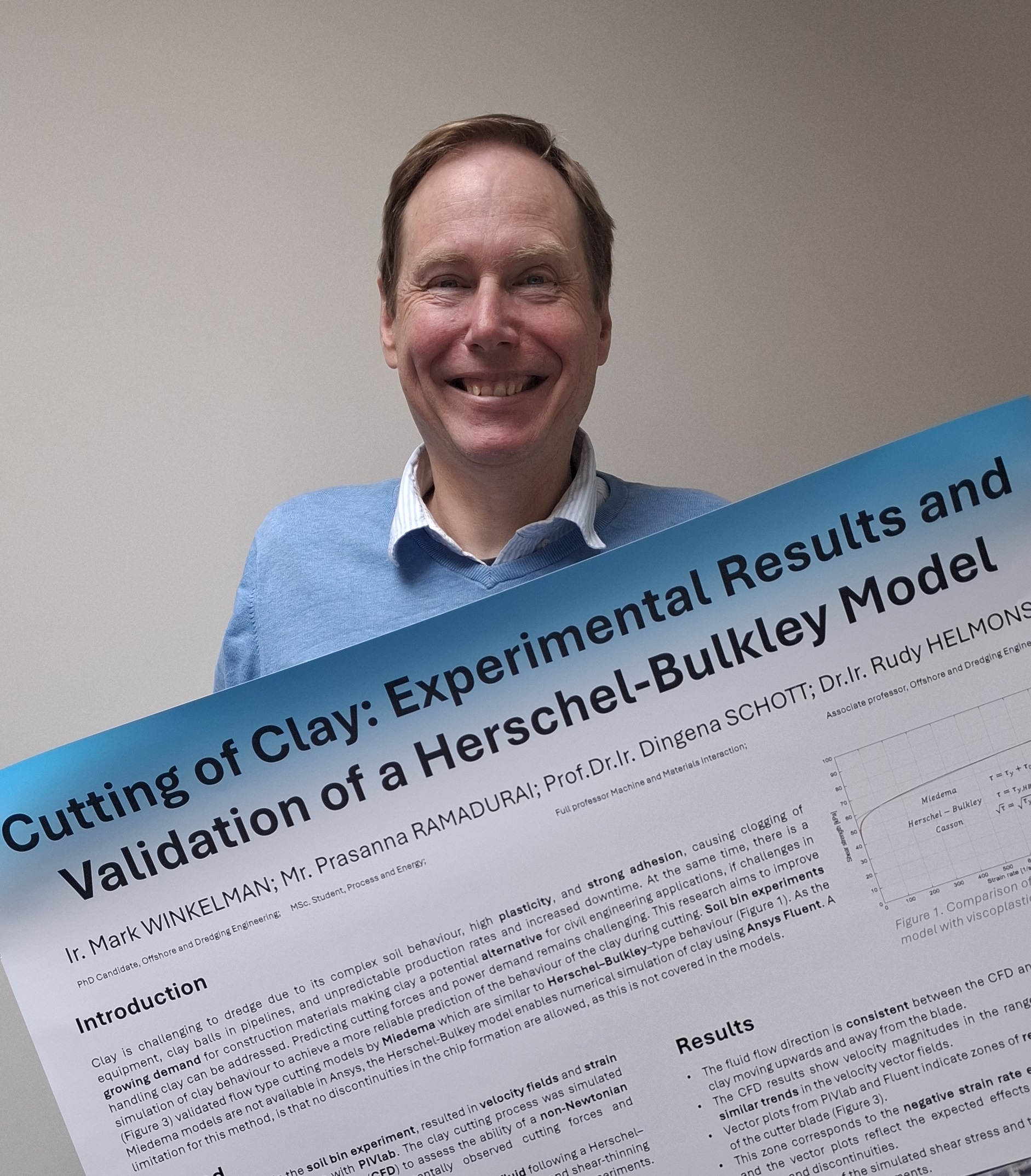
This week, I’ll be in Nantes at the Interpore 2026 conference1. This is an academic conference on everything porous, ranging from catalysts, to food, to foams, to biology and even soil mechanics. And that is a topic where my research fits in. I submitted an abstract for a poster on the work done by our intern Prasanna Ramadurai2 on the applicability of Herschel-Bulkley fluid modelling for the simulation of the cutting of clay. The accompanying presentation can be found here.
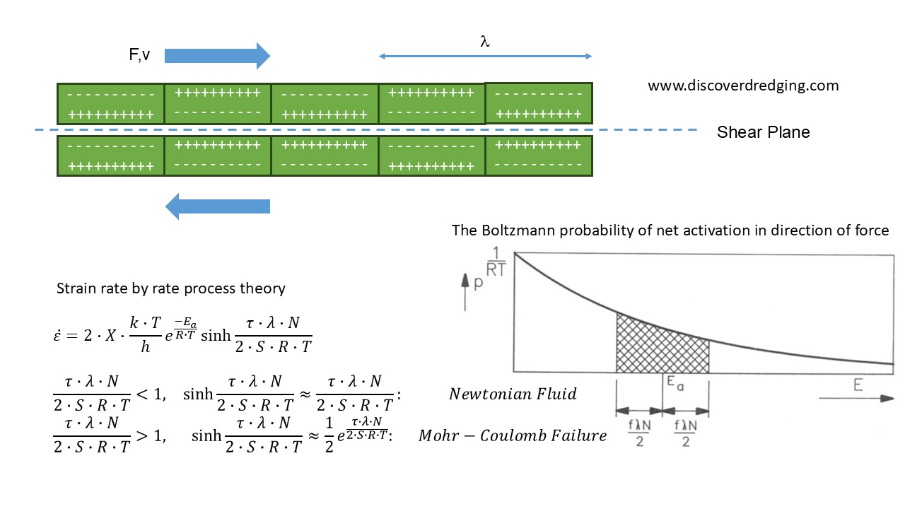
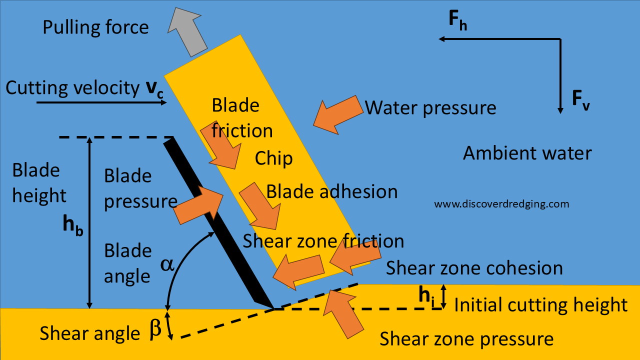
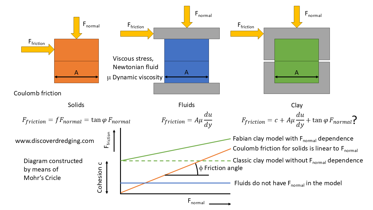
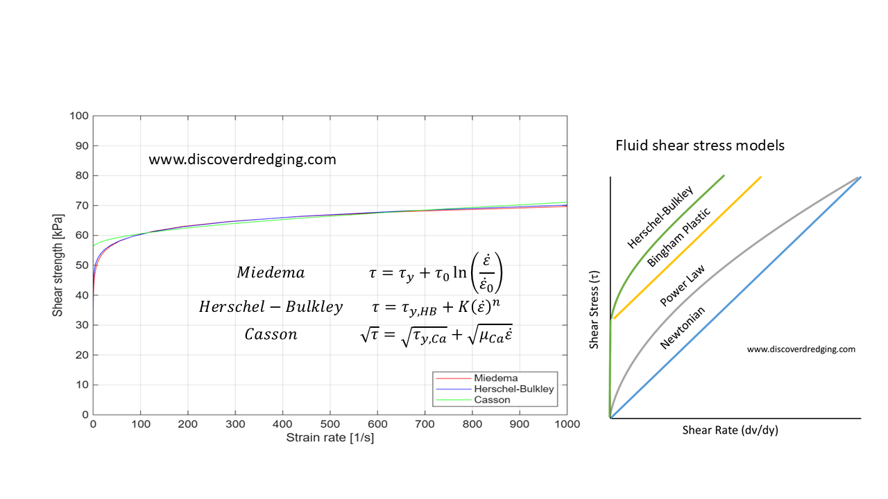
As a refresher, clay is a funny substance. The constituent particles of various minerals that form small plates, that are electrostatically charged. Due to these charges, they tend to cling together. When you deform the mass, there develops a shear plane. The particles move over each other with alternating repelling and attracting electric fields. This discrete path is reminiscent of how in particle physics moving steps are only possible when there is enough energy to push the particle past an activation threshold. This was initially postulated by Boltzmann3 and subsequently formalised by Arrenius and Glasstone in the rate process theory. Miedema further applied this to the deformation of clay4. Depending on the amount of water present, it can behave like the clay can behave like thick water or soft rock. Both captured by the same equations. Eventually the resulting shear stress curve is very similar to a Herschel-Bulkley fluid.
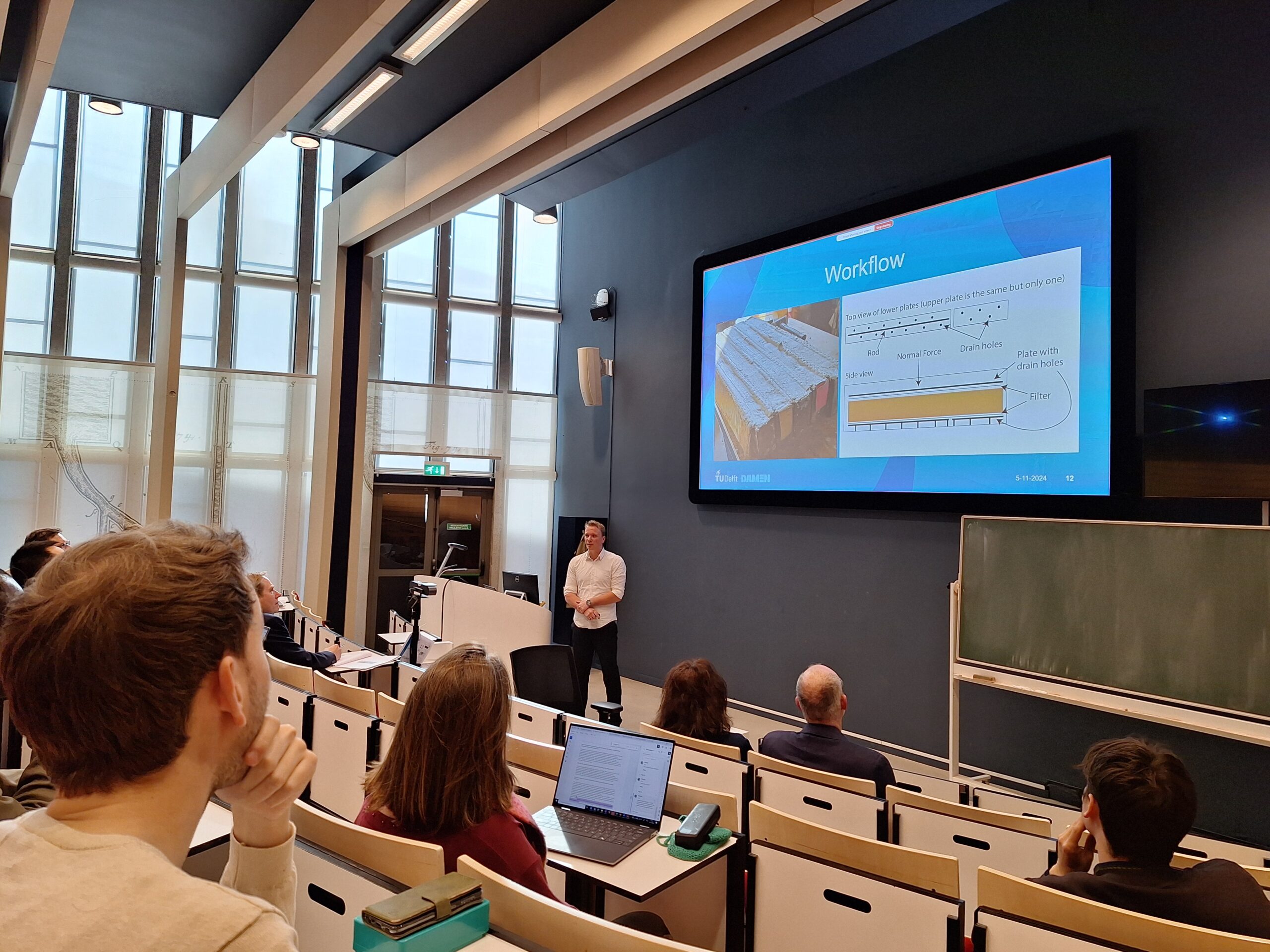
The work of Prasanna focused on exploring a workflow to simulate the deformation of clay using Ansys Fluent for CFD. This package does not support the deformation model as described by Miedema. But, as the resulting behaviour should be similar to the Herschel-Bulkley model, the H-B viscosity could be used. As previously described here, Prasanna managed to find the appropriate settings and setup to achieve credible results.
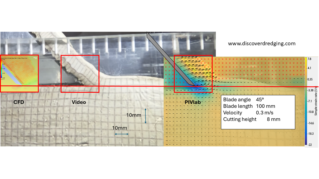
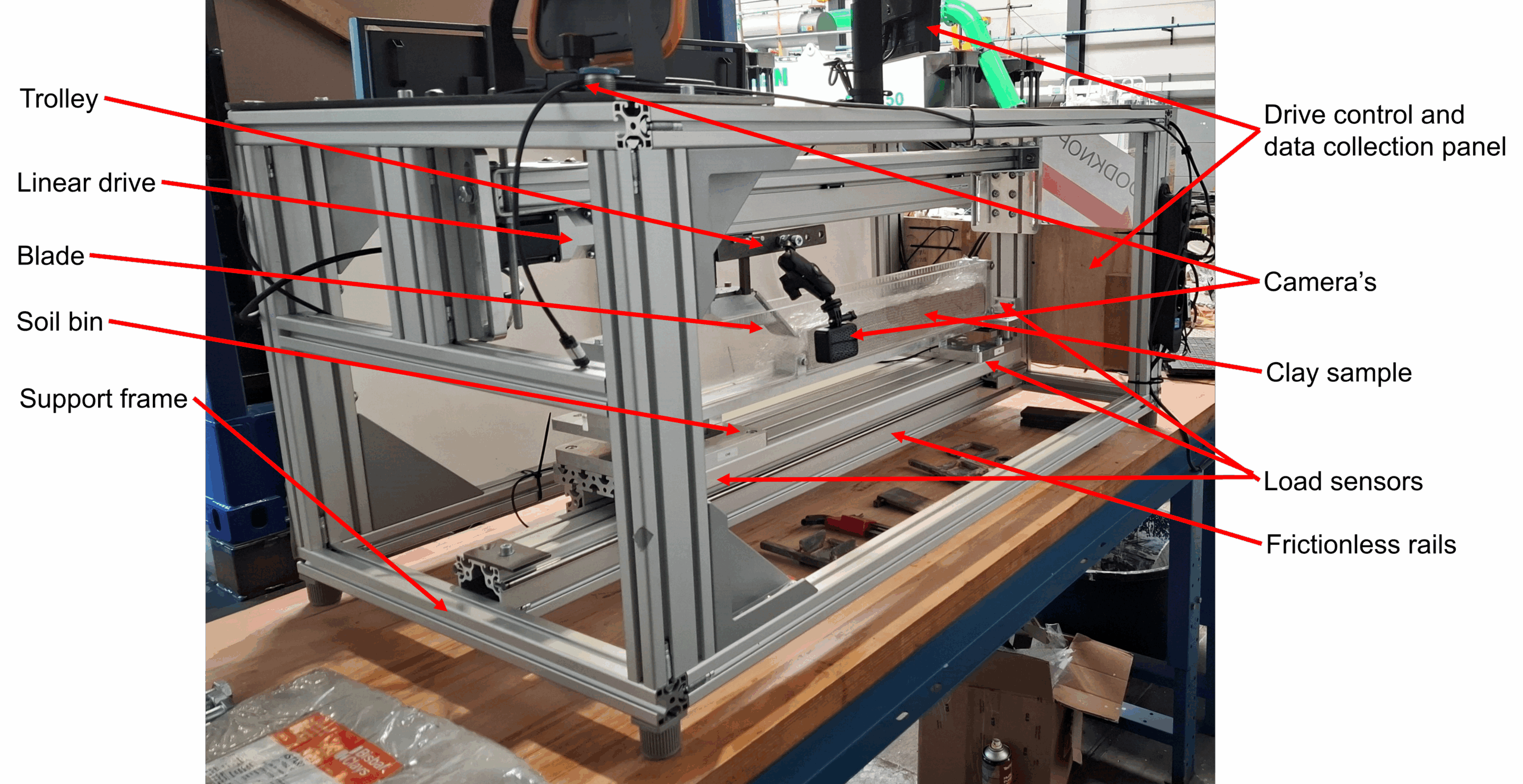
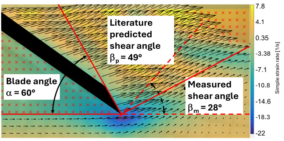
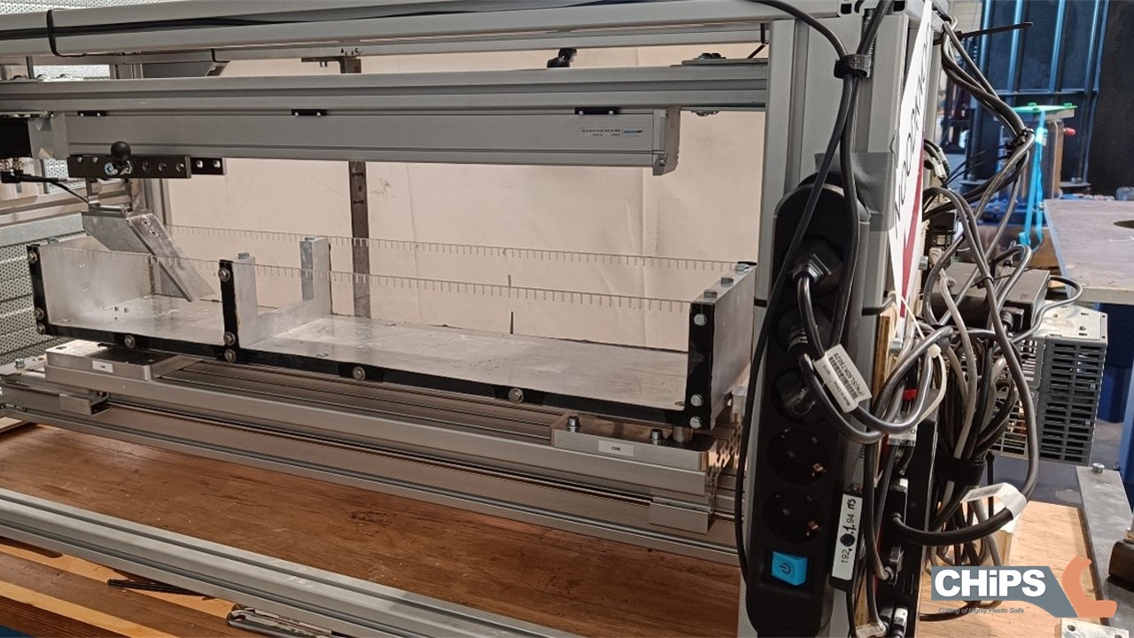
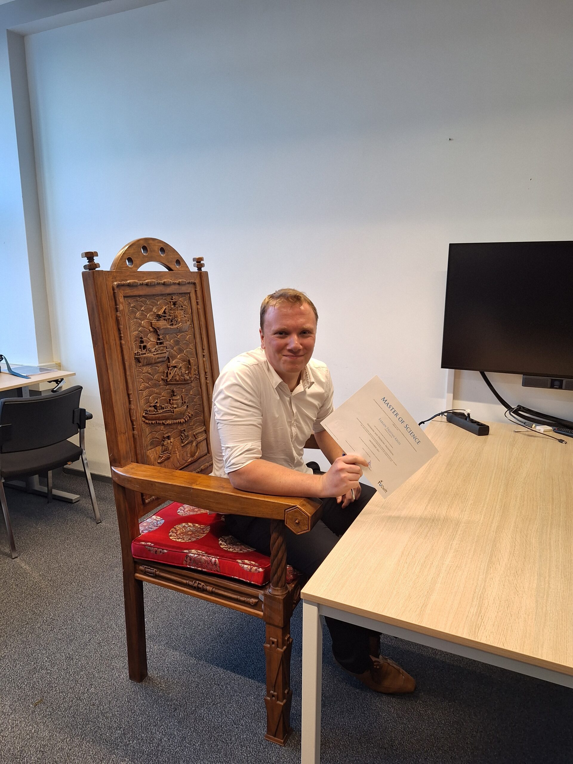
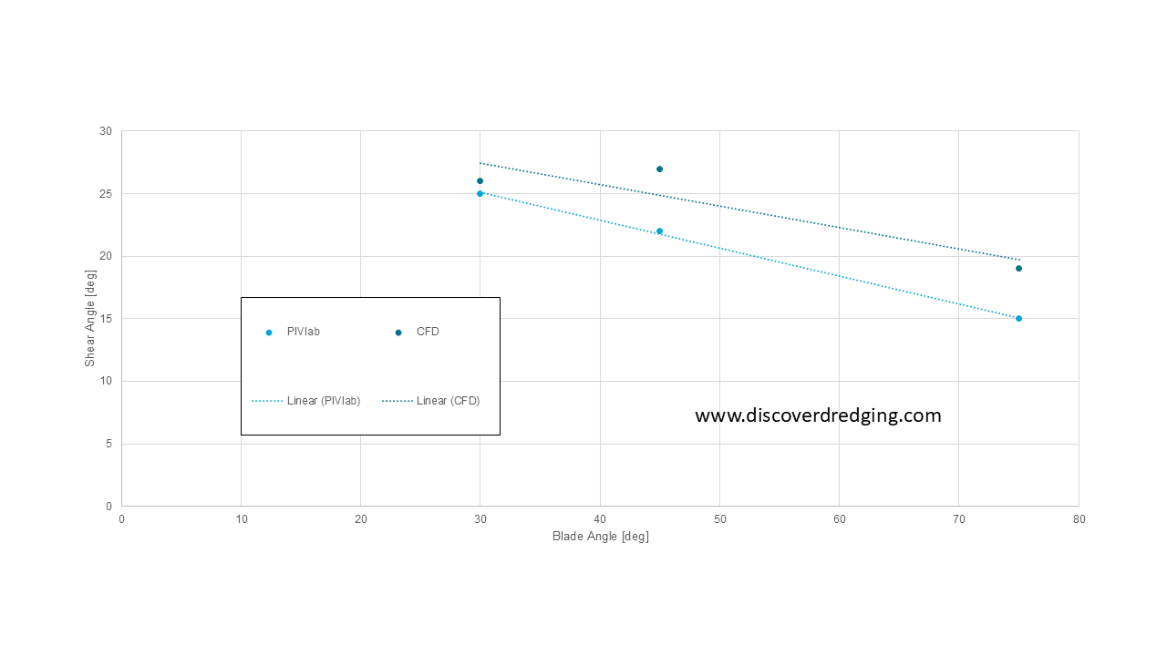
As Fabian Kruis5 has previously done experiments in the soil bin test rig, we do have reference data from actual measurements. Fabian has recorded the deformation and analysed the internal movements with PIVlab. The vector field from PIVlab is very similar to the vector field calculated by Ansys Fluent with the Herschel-Bulkley viscosity model. However, translating the deformation to stresses and ultimately to the cutting forces on the blade is still to be improved. The results from Ansys overestimate the measured forces.
Next to the poster, I also prepared a presentation. This presentation can be accessed through the conference portal, or directly from here. Off course, when you are at the conference, you can approach me there. Or through the contact details her on this website.
References
- 18th Annual Meeting & Conference Courses, Interpore 2026
- Internship Prasanna Ramadurai: CFD Modelling Clay as a Fluid, Discover Dredging
- Boltzmann constant, Wikipedia
- New Developments Of Cutting Theories With Respect To Dredging The Cutting Of Clay, ResearchGate
- Graduation Fabian Kruis: Modelling Friction In Clay, Discover Dredging