Graduation Luc Flake: Tear This Clay Block Open

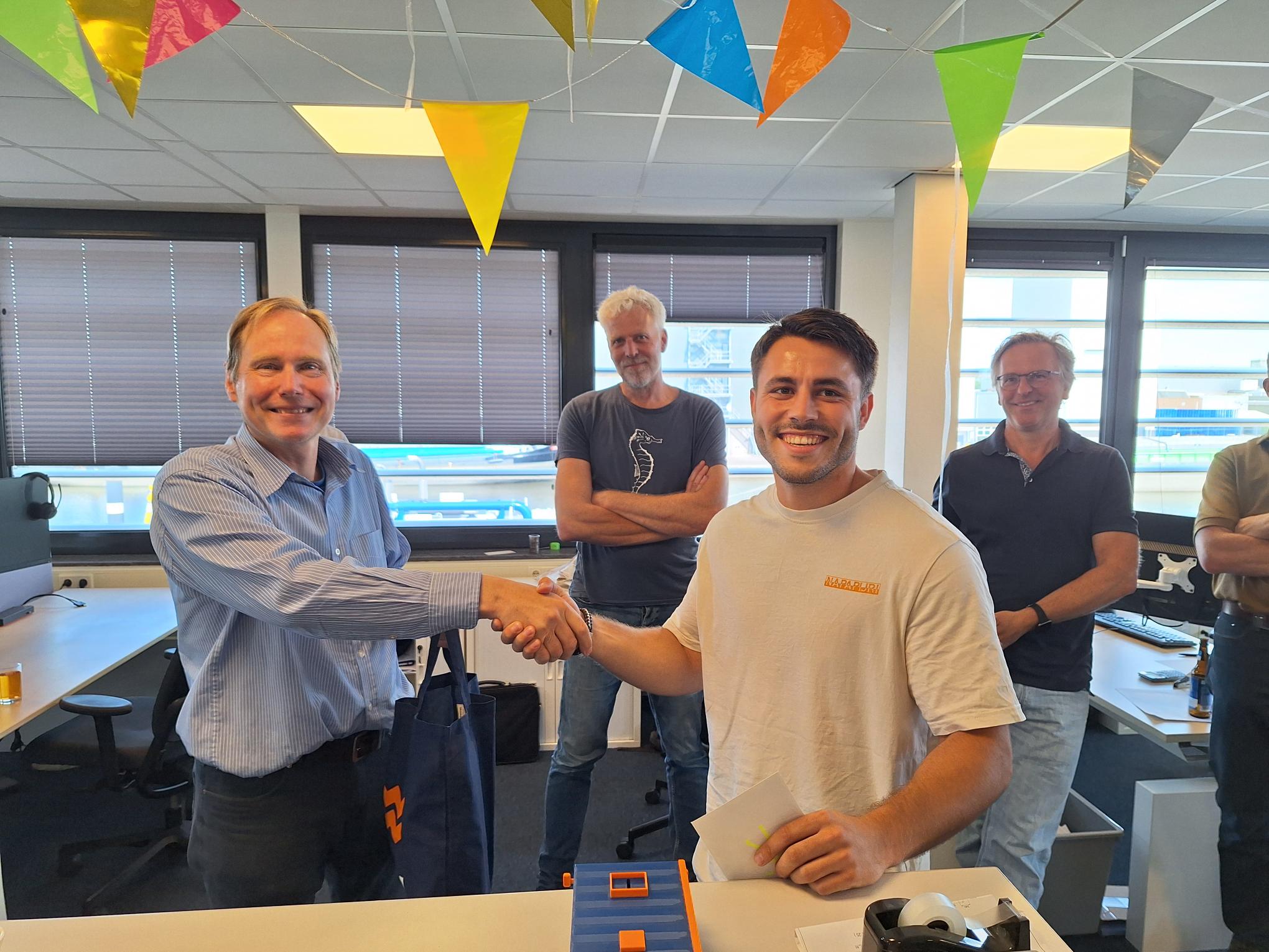
The graduation of Luc Flake celebrated at our department

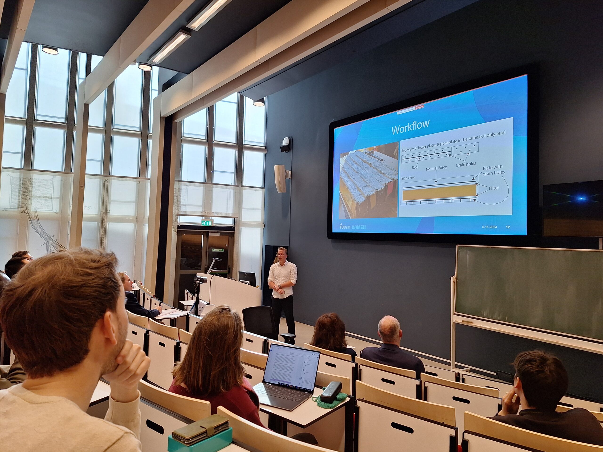
Recently, Luc Flake graduated on his bachelor project with us on the cutting of clay for my PhD research1. Anyone who has worked with clay cutting knows the challenge. Instead of breaking into manageable fragments, clay often behaves like a highly plastic material that flows continuously in front of the cutting tool. This flow-type behaviour can lead to cutterhead clogging, unpredictable production rates and increased cutting resistance. Unlike the research by Fabian Kruis who investigated the transition in cutting behaviour due to changes in operational parameters2, Luc was investigating the transitions due to the parameters of the soil itself.
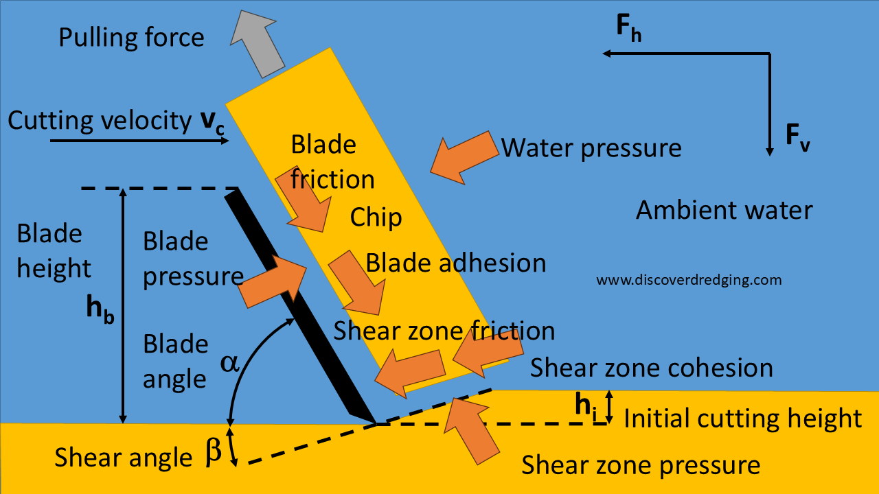
Forces involved in the cutting of clay

We previously found that the forces in the cutting process are influenced by more parameters than assumed in common clay cutting models. Especially the internal and external friction plays a role. Also, the adhesion not always has a fixed ratio to the cohesion. The result of these forces will change the normal forces in the shear plane. Under circumstances the normal force can change in direction. Instead of pushing on the plane, the chip will pull on the plane. Depending on the tensile strength of the clay, the shear plane will tear open and the cutting process transitions to the tear type. The internal angle of friction is a relatively known property of soil. Adhesion and external friction are usually not measured, but are relatively straightforward. The tensile strength of soil is a completely different animal.
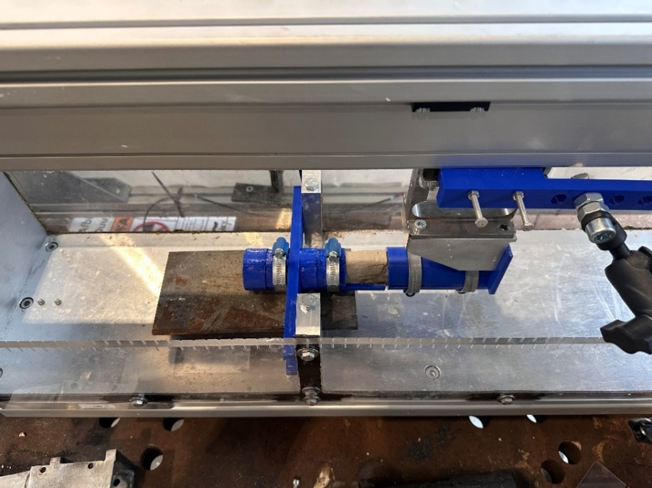
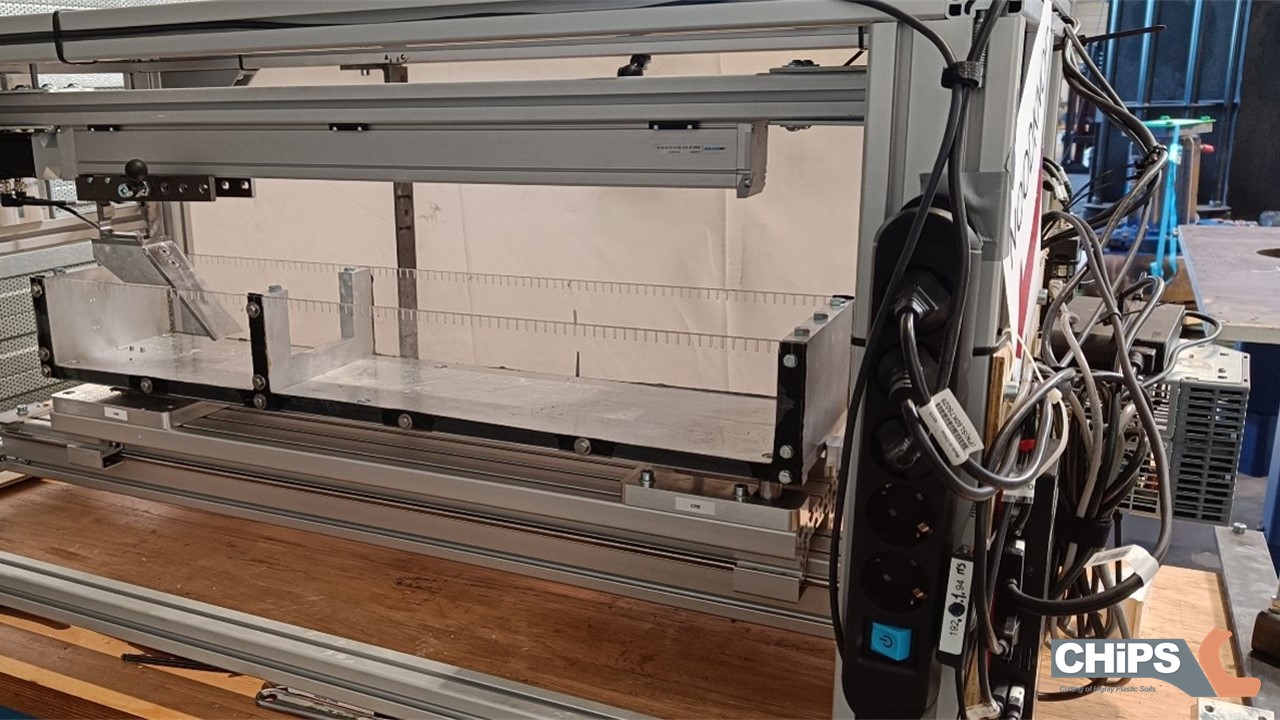
Modified testing rig to measure the tensile strength of clay

Proper civil engineers, like Luc nowadays, are used to putting things on top of other things. And gravity will provide for compressive stresses that keep the soil structure intact. We, as mechanical engineers, are more interested in destroying the structure and we are not afraid on pulling on materials. Civil engineers and mechanical engineers are even using different conventions for Mohr’s Circle. So, Luc had to devise a cunning plan to pull on the clay and find the tensile strength. He modified the test rig and had a special bracket printed to clamp the clay.

Tensile strength depending on the sand content of clay

In order to modify the soil properties of clay, Luc gradually added sand and tuned the water content until the adhesion and the frictions reached the desired values. The resulting wet clay-sand mixture was consequently tested for tensile strength. As expected the tensile strength of the clay reduced as more sand was added. You can imagine that loose sand and no clay does not have any cohesive strength and consequently no tensile strength. Remarkably, there is a sand clay ratio that exhibits a slight local increase in tensile strength. Together with some other finds, we gained more insight in what we can expect of the different soils for the cutting process and how our dredges will perform in those conditions. Next to the usual test outputs, Luc also made some beautiful 3D scans of the resulting chips and block surface. These pictures are a very interesting for my research and will probably the topic of another post.

Luc, thank you for your contribution to my research project.
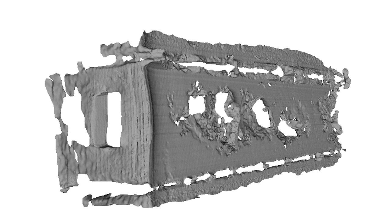
3D Lidar scan of a freshly cut block of clay

References

  1. Tag: PhD Project, Discover Dredging
  2. Graduation Fabian Kruis: Modelling Friction In Clay

WODCON 2025: Rolling Out A New Clay Test

Fully covered cutter head in sticky clay

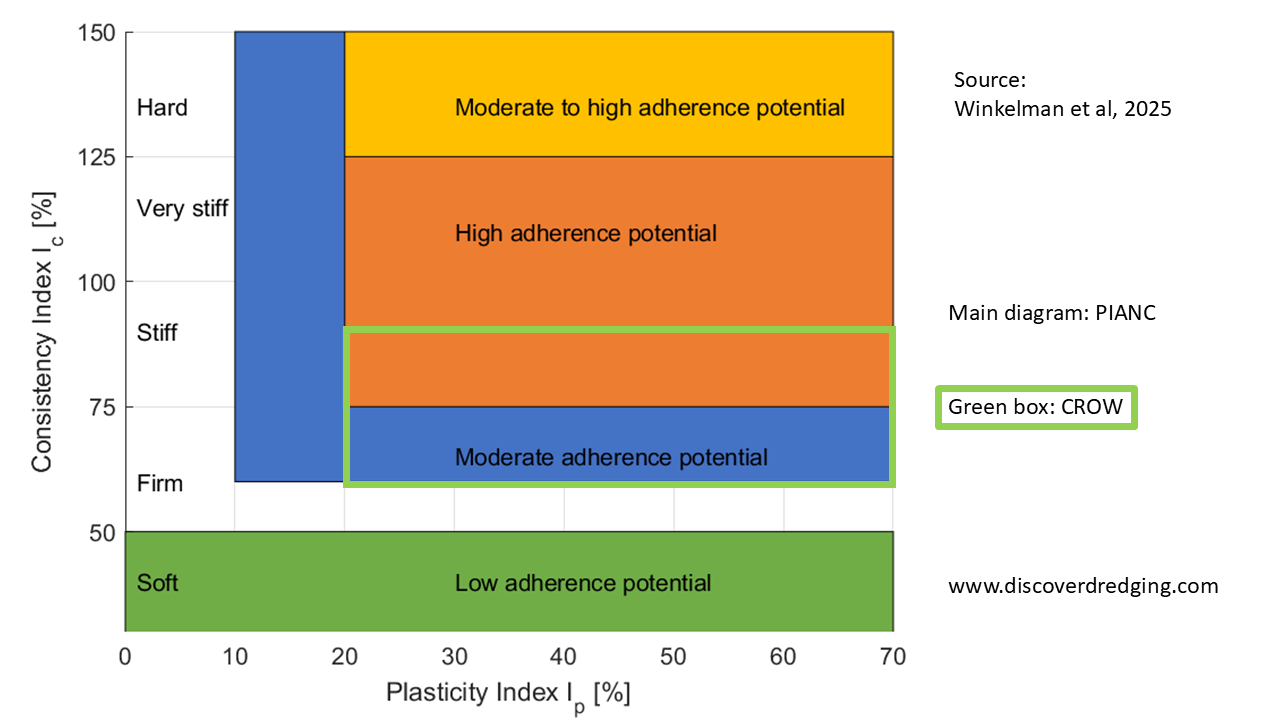
Here at the WODCON 2025 in San Diego1, the theme is ‘Dredging Towards a More Resilient Future’. One of the challenges we encounter, is that even the resources of good construction sand run out. We either have to repurpose sand already dredged or find and alternative construction material. One such an overlooked material is clay. A lot of effort is put into understanding the behaviour of clay in infrastructure applications. The Dutch Centre for Legislation and Infrastructure (CROW)2 has provided recommendations on the applicability of clay for various types of construction. However, the clay has to be dredged and for the adherence potential of clay, there is another recommendation issued by World Association for Waterborne Transport Infrastructure (PIANC)3. Both do use the Plasticity Index and the Consistency Index as criteria to classify the clay. Interestingly, the clay type that is regarded as suitable for construction by the CROW, is also classified by the PIANC as to have the highest adherence potential and thus gives the most problems in dredging.

Criteria of PIANC and CROW compared

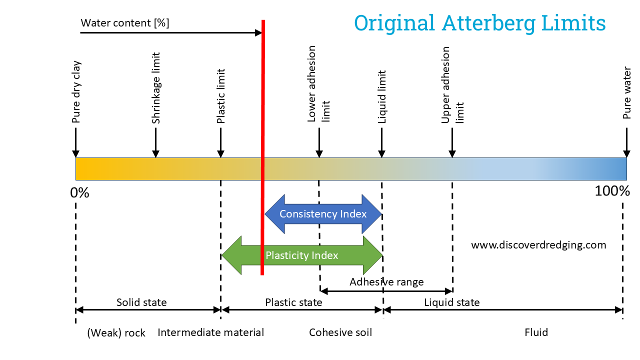
Another problem with the criteria by PIANC is that they tend to be unreliable. Something they already acknowledge in the supplied explanation to the diagram. When following the literature that led to the recommendation, it turns out the original application was not dredging but tunnel boring4. Where the problem was not so much the clogging of the cutter shield, but the collection of clay in the suction chamber. And even plotting the data used for this assessment shows a large variability. Apparently there is more to the problem of adherence than just the PI and CI. Which might be obvious when considering the original Atterberg Limits. The PI and CI are related to the plastic range of clay, whereas Atterberg already defined a range where adhesion is more relevant.

Relation of PI and CI to the adhesion range according to Atterberg

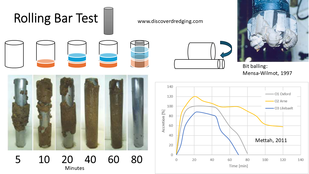
A situation similar to the cutter clogging is the covering of a drill bit in the oil industry. There, they encounter a phenomenon called ‘Bit Balling’5. It is extremely difficult to assess the bit balling potential from a physical model related to the soil parameters alone. As a solution they developed the ‘Rolling Bar Test’6. A defined amount of clay sample is put into a cylinder with the needed amount of water. Finally a rod is inserted in the sample cylinder. The whole contraption is placed onto a roller set and turned for a set of times. Each time the amount of clay sticking to the rod is measured and plotted in a graph. Eventually, most clay types will loosen their grip on the rod. But some are sticking to the rod indefinitely. Those are the clays that are also likely to show bit balling in the actual process.

Bit balling and procedure of a rolling bar test (data: Mettah, 2011)

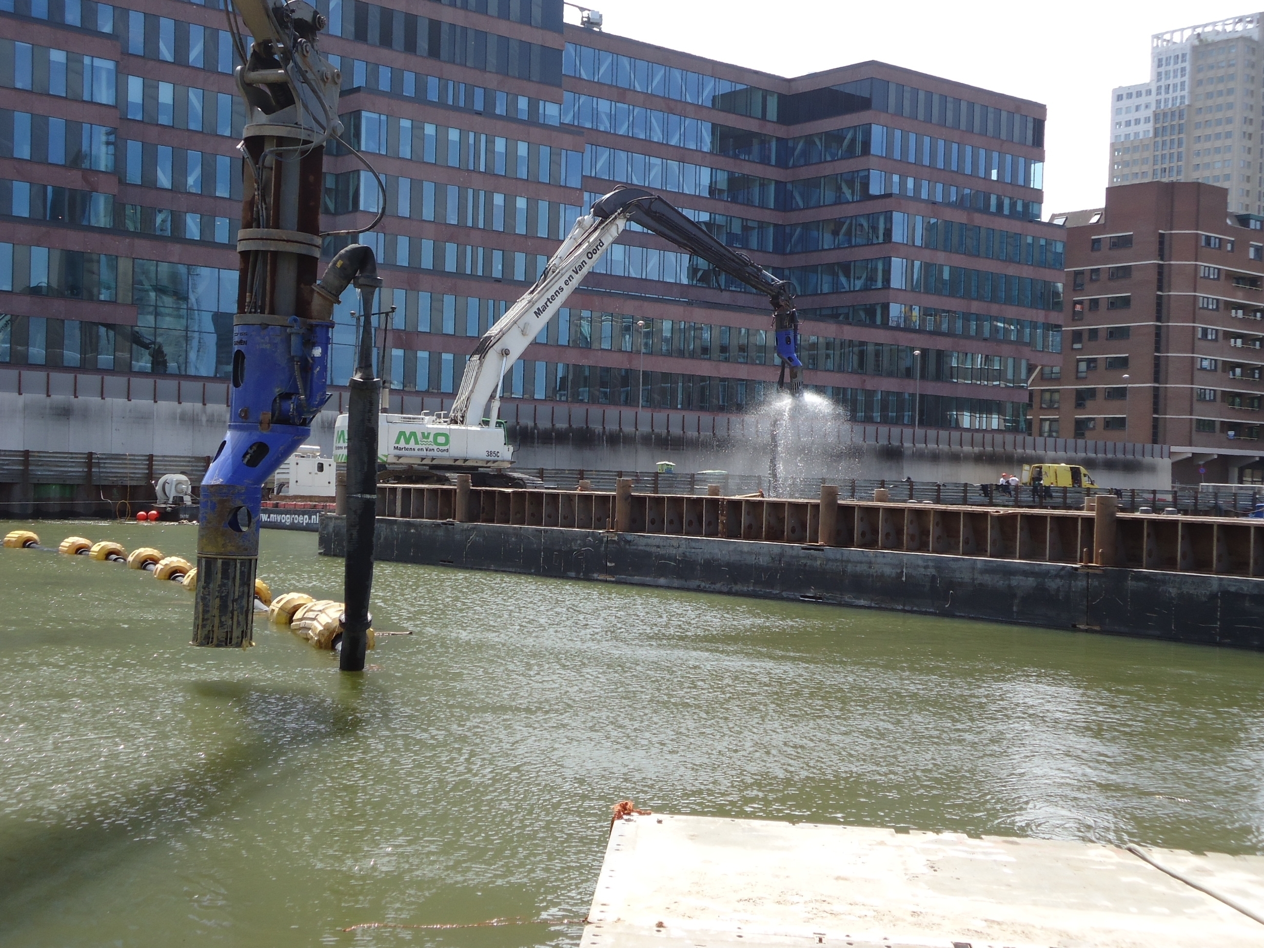
As we know that we can’t fight the adhesion of clay, we may as well improvise, adapt and overcome the problem. Since already my graduation, I am working with clay. In that case, it was an auger, that needs the adhesion to the back shield to propagate the clay in the auger. When we were asked by a contractor to improvise a tool that could tackle this sticky clay, we developed a disc bottom cutter head that used the adhesion to move the clay over the blade to a scoop behind the blades. This worked so smoothly, that the satisfied customer bought a second. Eventually he finished to job in time and in budget7.

DOP pumps with special clay cutter head at the ‘Markthallen’ project in Rotterdam

References

  1. 24th World Dredging Congress & Exhibition
  2. Materialen in (constructieve) ophogingen en aanvullingen; Richtlijn ter beoordeling van alternatieven voor zand, CROW
  3. Classification of Soils and Rocks for the Maritime Dredging Process, PIANC
  4. Adhäsion von Tonböden beim Tunnelvortrieb mit Flüssigkeitsschilden, Thewes
  5. PAO lubricant inhibits bit balling, speeds drilling, Mensa-Wilmot
  6. The Prevention and Cure of Bit Balling in Water-Based Drilling Fluids, Mettah
  7. The Origin of Clay, When Dredging Becomes Sticky, Discover Dredging

See also

Graduation Fabian Kruis: Modelling Friction In Clay

Fabian Kruis presenting his graduation research

Fabian Kruis graduated on his master thesis at the Delft University of Technology on a project for my PhD research1. He investigated the cutting behaviour of plastic clay. As it was the first time we are now actually using the test rig designed by Ines2, he first had to do was a lot of trouble shooting for commissioning the test rig. Spoiler alert: the cutting forces were much higher than expected and the linear drive was not strong enough to cover the whole range of experiments we’ve wanted to do.

Clay cutting test rig at DDE in Nijkerk

The cutting forces involved with cutting of clay are acting on all four sides of the simplified chip. On the outside, there is the barometric pressure of the surrounding water. On the far end, there is an unknown and hard to determine force from the rest of the chip that is not in contact with the blade anymore. At the shear plane, there are the normal force, the internal friction and the cohesion. At the blade, there are the normal force, the external friction force and the adhesion. The sum of these last three forces will give the cutting force we are looking for, as they make up the required cutting power on the drive. But they can only be calculated, once the other forces are known.

Overview of all the forces involved with the cutting of clay, acting on the chip

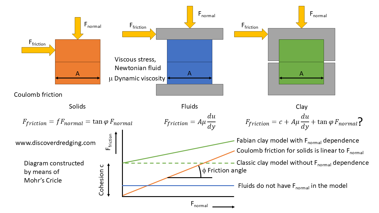
Fabian’s assignment was to have our own experience with the cutting of clay and check whether the models used in the dredging industry have any reliability in predicting the cutting forces. checking whether all assumptions and simplifications were justified. e.g. Plastic clay does have similar properties and behaviour as a fluid. And a fluid does not have an internal friction. Consequently, clay should not have an internal friction also. Right? When there is no internal friction, there can’t be an external friction either. Right, right? Fabian tested these assumptions by actually performing shear tests on internal and external planes.3

Explanation of internal friction for solids, fluids and clay

At least for the clay we used in this research, he already found that the assumption for ‘no friction in clay’ is not valid. Consequently, this had knock on effects on the rest of the cutting force calculation. We did find a different behaviour, the shear plane was off and the cutting forces were indeed much higher than expected. It is now up to me to use Fabians results and model modifications to implement into my own research. As a matter of fact, I used part of his thesis to write an article and hope to present this soon. I’ll keep you update on those developments.
As we are very satisfied with Fabian’s work and him as a person himself, we offered him a position in our team at Damen Dredging Equipment in Nijkerk, which he happily accepted. So, next to progress for my research, we have a new colleague. Welcome Fabian, thank you!

Fabian signing his MSc. certificate.
Fabian signing his MSc. certificate sitting in the ‘dredging chair

References

  1. Personal Announcement: Going Back To School To Cut Some Clay, Discover Dredging
  2. Graduation of Ines Ben M’hamed: The Strength of Clay in a Test Rig, Discover Dredging
  3. Direct shear test, Wikipedia

See also