ISFOG 2025: Commissioning The Test Rig And Reporting To Academia

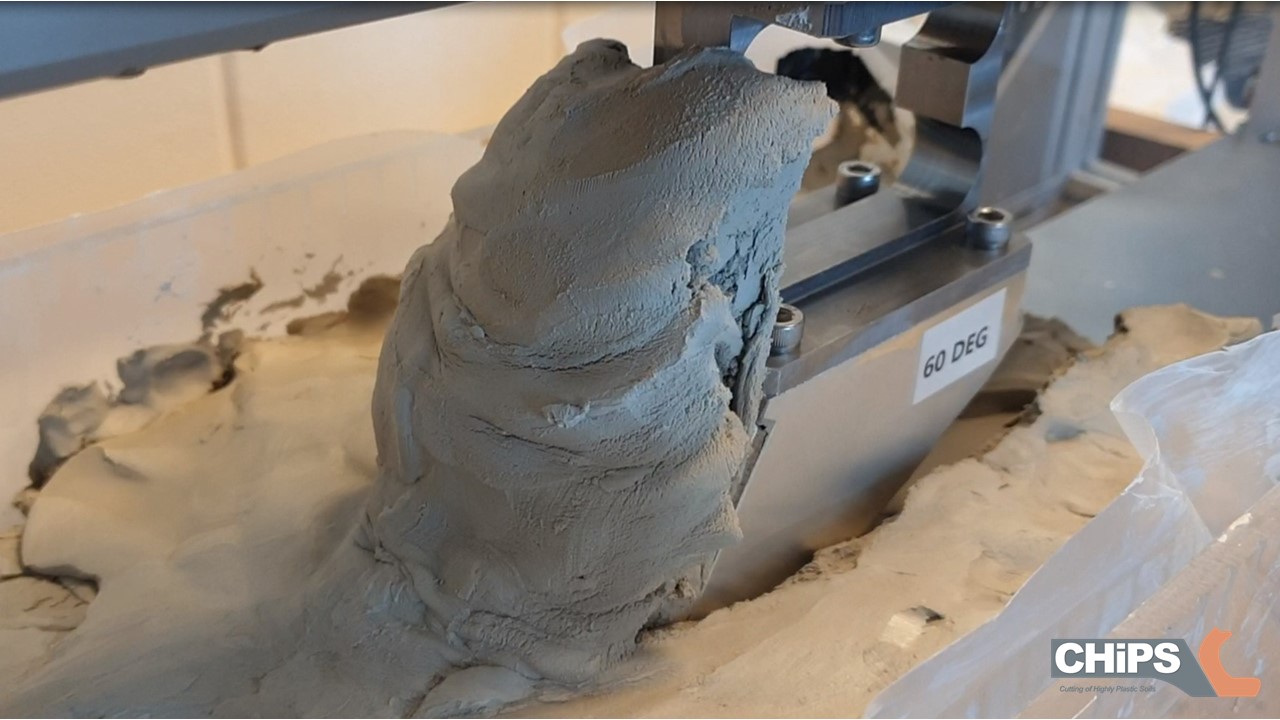
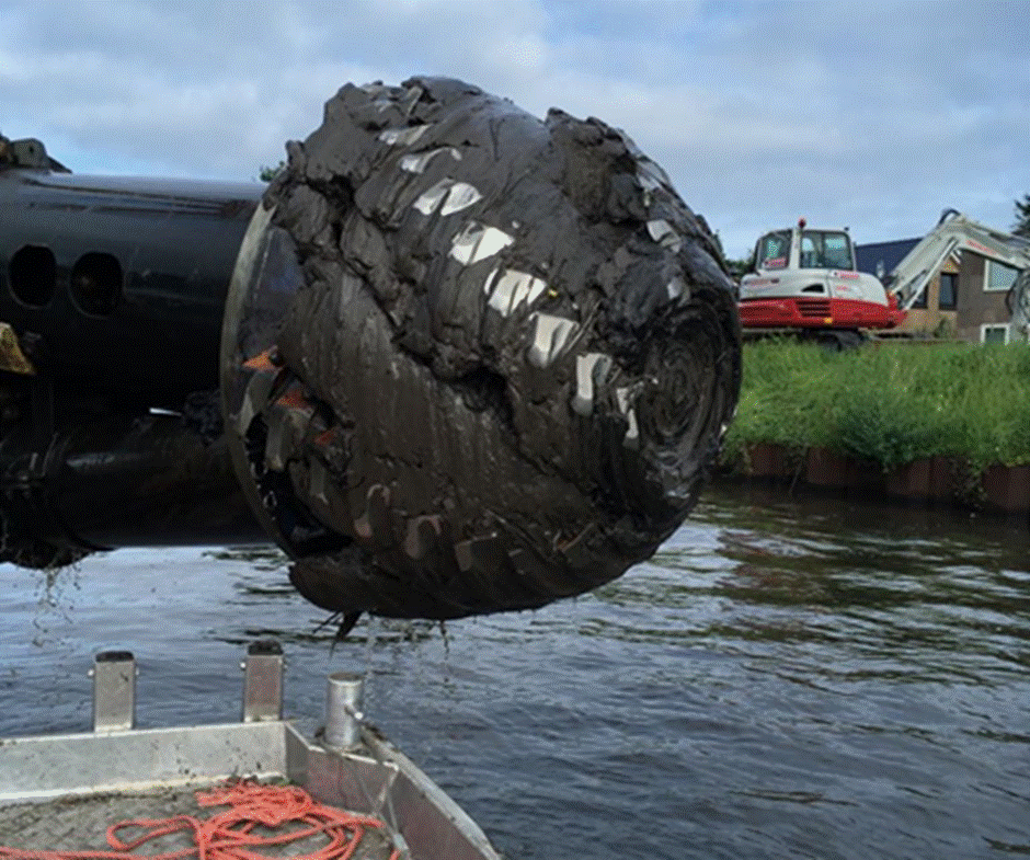
Fully covered cutter head in sticky clay

Fully covered cutter head in sticky clayThis week, I will be presenting my paper1 about the initial experiments on the test rig at the 5th International Symposium on Frontiers in Offshore Geotechnics (ISFOG 2025)2. I will be there in the breaks to explain my poster3 in the lunch breaks. For my audience not present at the symposium, I can highlight the most interesting parts here. I presume, most of you are aware of the operation of a Cutter Suction Dredge and also know about its problems when working in clay. The clay will adhere to the teeth and arms and clog the cutter head. This leads to interruption of the project and in consequence: time and cost overruns. Also, the production itself is difficult to calculate. This is why we at Damen Dredging Equipment started the CHiPS project with the TU Delft4 to investigate the process, improve the estimation model and optimise the design of the cutter head for operation in clay.
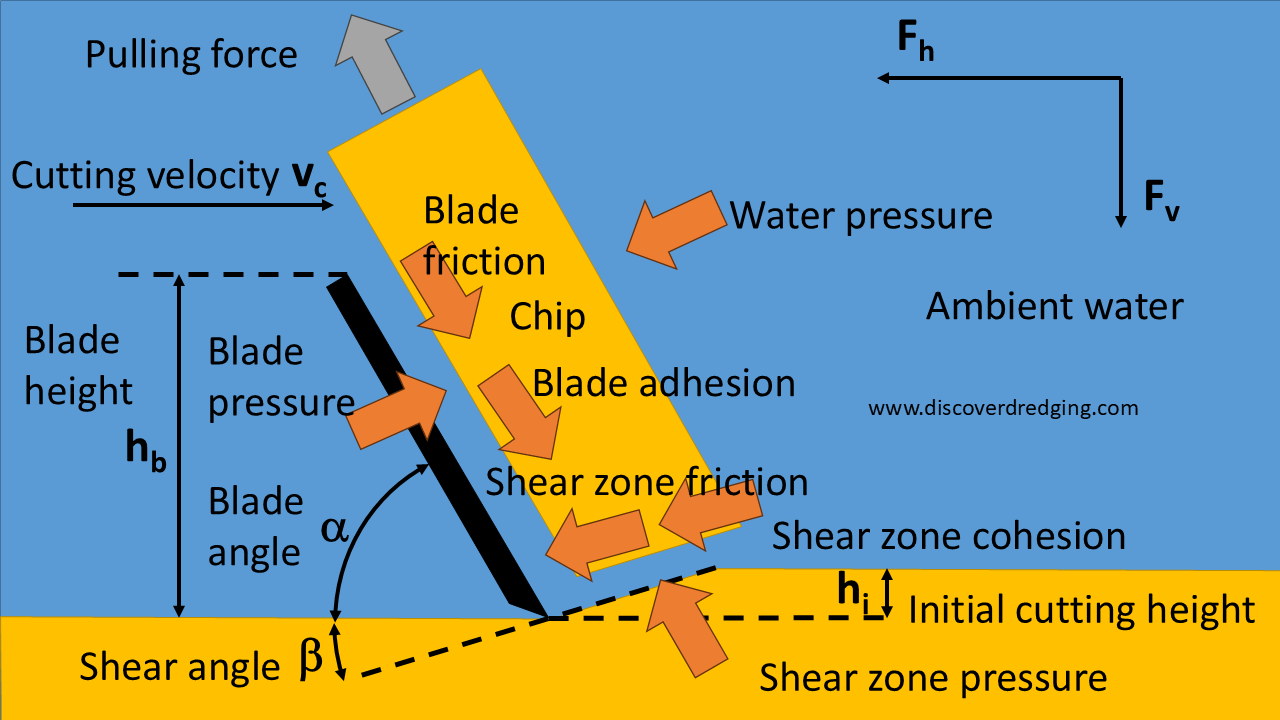
Forces involved in the cutting of clay

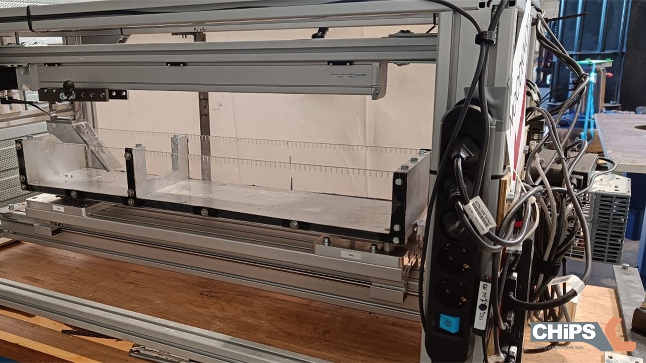
Forces involved in the cutting of clayFor this purpose, we constructed a linear cutting test rig. Last post about the graduation of Fabian Kruis has more on the results of his thesis5. In the ISFOG article, we wrote about the design and performance of the rig and the opportunities it provides for further research. The design criteria for the rig as was laid down in the assignment for Ines Ben M’hamed were6:

  • Identifying the main parameters influencing the cutting forces and the cutting regime.
  • Designing general arrangement for testing linear cutting models.
  • Capture the signals for force and deformation.

The developed test rig was inspired by the model described by Hatamura and Chijiiwa7. The blade is attached to a linear moving trolley, cutting through a block of clay mounted in a frictionless moving soil bin. The reaction forces on the box are measured. and images of the grid printed on the side of the clay block are captured with a GoPro camera of later evaluation with PIVlab®. A set of 30 experiments was defined according to the Buckingham-PI method as presented at the CEDA Dredging Days last year8.
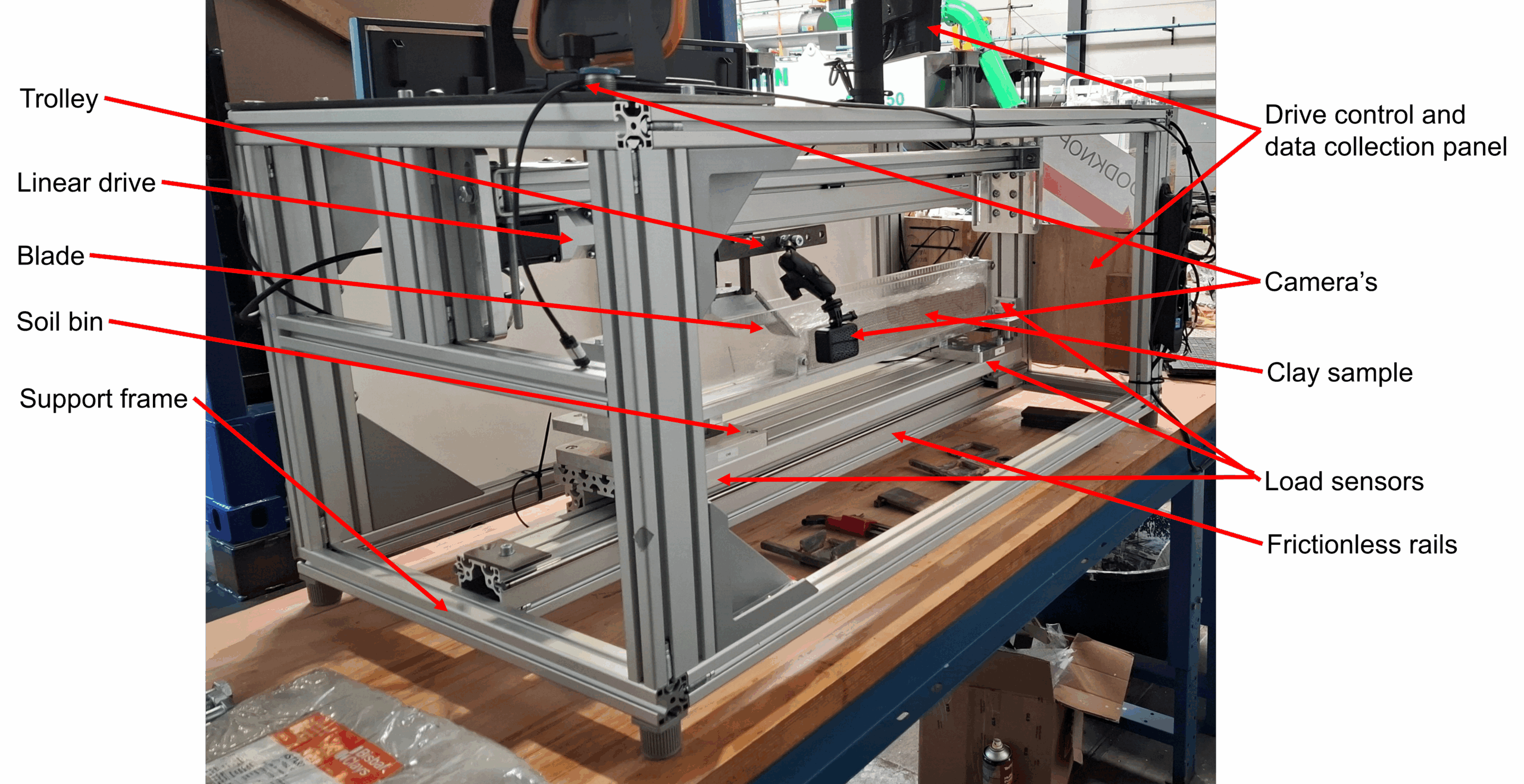
General arrangement of the linear cutting test rig

Next to the cohesion and adhesion, the tensile strength of the clay had to be measured to obtain a consistent result. We could confirm the linear relation between cutting depth and the cutting force as predicted by existing models from literature. As we were using modern techniques for capturing images, we were able to accurately measure the displacements with the PIVlab® application. The good results are due to the novel printing technique developed by Fabian Kruis, to apply a grid on the side of the clay sample. One remarkable result is, that most models for the calculation of the sliding forces, only take adhesion into account, but measurements indicate that the external friction cannot be neglected. This appeared in the measured shear angle, which was much lower than the shear angle predicted by existing models.
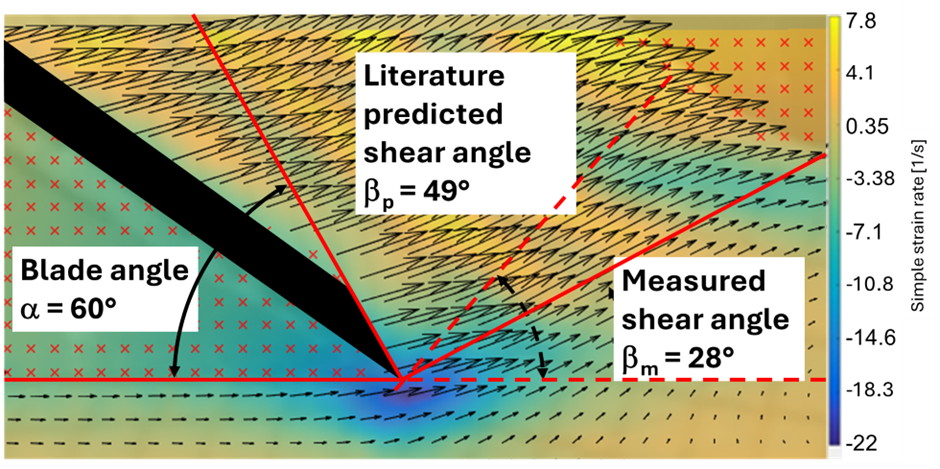
Captured deformations in a vector field. Note the differences in shear angleCaptured deformations in a vector field. Note the differences in shear angle

The experiments yielded a treasure trove of measurements, we are still analysing them. e.g. We noticed some strange reversal of the vertical cutting forces. And we are interested in the transition from one cutting regime to another. Those results will be presented in my next journal paper. In the mean time I am watching all those captured movies over and over again. To me it’s very inspiring and I like to share an example.

A slow motion movie of a clay cutting experiment (ASMR)

References

  1. Cutting of highly plastic clay: analysis of large rapid deformation processes, Winkelman (paper)
  2. 5th International Symposium on Frontiers in Offshore Geotechnics, ISSMGE
  3. Cutting of highly plastic clay: analysis of large rapid deformation processes, Winkelman (poster)
  4. Personal Announcement: Going Back To School To Cut Some Clay, Discover Dredging
  5. Graduation Fabian Kruis: Modelling Friction In Clay, Discover Dredging
  6. Graduation of Ines Ben M’hamed: The Strength of Clay in a Test Rig, Discover Dredging
  7. Analysis of the mechanism of soil cutting (1st report, Cutting patterns of soils)
  8. CEDA Dredging Days 2024: My Presentation On Clay Cutting, Discover Dredging
See also

CEDA Dredging Days 2024: My Presentation On Clay Cutting

Initial clay cutting tests for my PhD project CHiPS

Next week is the biannual CEDA Dredging Days event1. This time fully focused on presentations, networking and having a good time together with like minded people. Since a long time, it will not be in conjunction with the distractions of the Europort exhibition. Instead, it will be in the impressive WTC Rotterdam. This is an excellent opportunity to share with you the progress of my PhD project on clay cutting at the TU Delft2. As a teaser, I would like to share with you some observations from my literature study, already3. Starting to search for literature via Google results in this:

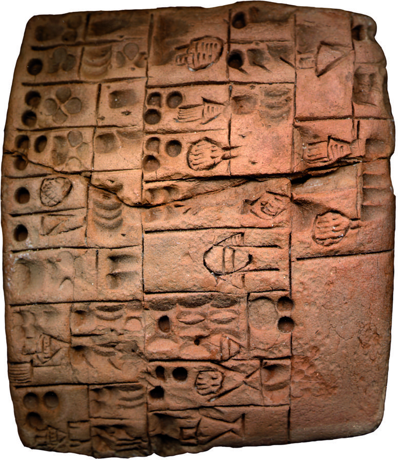
Literature on clay (Kushim, 3400BC)4

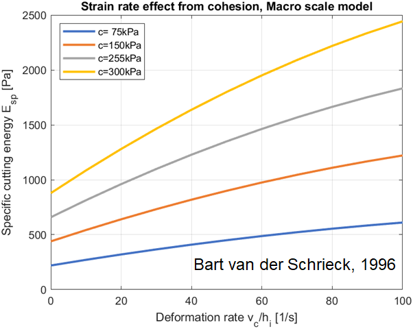
When estimating the cutting production of a dredge, the objective is to find the specific cutting energy for that dredge in combination with the soil properties and correctly chosen operational settings. The specific cutting energy is the amount of power needed to excavate a volume of soil from the bottom5. The funny thing is, when you work out the dimensions of the specific cutting energy, the unit is similar to a stress or pressure. So, there should be a direct relation between the specific cutting energy and a soil property. But which one? For cohesive soils as clay, there are: shear strength, cohesion, adhesion, tensile strength, yield strength. The VOUB course6 recommends to use an empirically derived relation between the cohesion and the deformation rate (which in turn is based on the operating settings) for the specific cutting energy.

Specific Cutting Energy Empirical (Bart van der Schrieck, 1996)

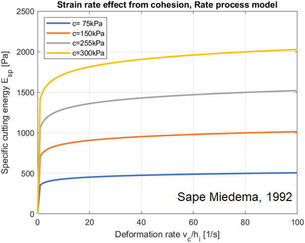
In contrast to this empirical model, one could also start at the displacements of the clay particles and model the implications for the larger continuum mathematically. This has been investigated by Sape Miedema, who has published countless articles and an impressive book on the topic7. Following this through, the estimated specific cutting energy is in the same range as the empirical model. However, on closer inspection, there are some variations on the outer limits of the deformation rate.

Specific Cutting Energy Theoretical (Sape Miedema, 1992)

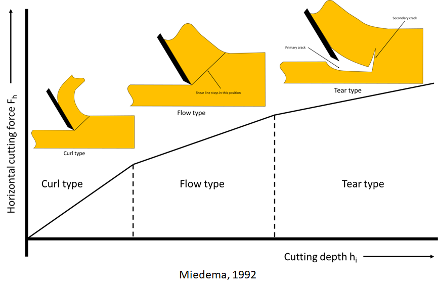
This discrepancy is probably due applying the model under all conditions. Miedema already recommends to check for the validity of the assumptions in the model. At very thin cutting layers, the resulting chip may form a long curl. When cutting thick layers, the blade will cut out chunks. And those cutting types will have different force equilibriums, resulting in different cutting forces. Miedema suggested a three regime map of cutting types, which coincidently resembles the curves found empirically.

Cutting types (Sape Miedema, 1992)

It appears, there are many more cutting types possible for a myriad of soil properties and operating conditions. However, the published results and proposed models are not directly applicable for the dredging industry. Either the conditions or assumptions differ (dry earth works for example) or parameters or data has been failed to included in the publication. This leads to some white spots in the knowledge that I hope to colour in with my future models and upcoming experiments8.

Clay cutting test rig at DDE in Nijkerk

References

  1. Welcome to CEDA’s (revamped) Dredging Days 2024
  2. Personal Announcement: Going Back To School To Cut Some Clay
  3. CEDA Announcement of my presentation, LinkedIn
  4. What was the first (known) maths mistake? Matt Parker
  5. Experiencing The Cutting Edge Of Dredging Technology
  6. VOUB Cursus 1998, Deel X, hoofdstuk 12, VBKO
  7. The Delft Sand, Clay & Rock Cutting Model, Sape Miedema
  8. Mechanical excavation of clayey soils, a review of the physical phenomena occurring, Mark Winkelman et al (CEDA Dredging Days 2024)

See also

Graduation Omar Karam: Rock Cutting The Egyptian Way

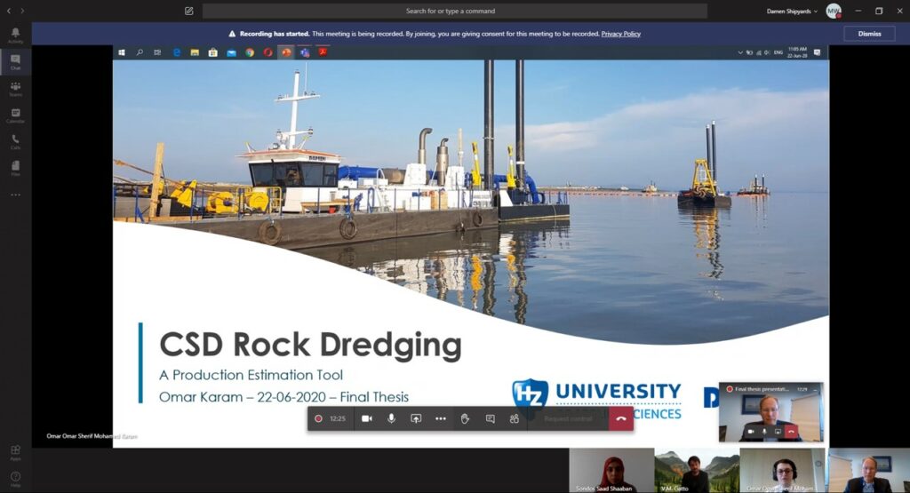
Graduation presentation of Omar Karam

Egypt is a great nation when it comes to ancient engineering. No other country has such a concentration of impressive monuments and such an interesting history as over there. If you are not convinced that modern Egyptians are not capable of great engineering feats you are wrong. Last Monday, Omar Karam graduated at our R&D department of Damen Dredging Equipment1 on his thesis about ‘CSD Rock Cutting.’

Cutting processes have been extensively described by Sape Miedema in ‘The Delft Sand, Clay & Rock Cutting Model’2. Omar has been using the frame work of Miedema to make some useful tools for the estimation of the production of our dredging equipment in rock. In due time, you will find the results of his thesis in the online dredge selection tool ‘Sandy’. Omar’s curiosity and ingenuity does not end here. He will continue studying at a university, but I do hope to meet him again, as he would be a valuable asset for our dredging community. Keep an eye out for him.

Program structure diagram of cutting force calculations

His graduation brings me back to my first lessons in dredging technology at the Delft University of Technology by the illustrious professor de Koning. In a sense he was an old school engineer, who hammered it in to us that thinking is done by doing it with your hands3. Back than the Polytechnic School was just rebranded to University and he was mocking that as a university, we had to set the topics in a broader perspective. So, he started his introduction on cutting technology with some slides of the unfinished obelisk at Aswan4 as every aspect of the cutting process could be illustrated.

Phases of chip forming in rock cutting

The story according to de Koning is: ‘Around the quarry of the obelisk, they have found diorites5. These are some sort of volcanic balls of rock. In combination with the marks and scratches all around the obelisk, archaeologists believe these stones have been used to pound the granite. The impact compresses the bedrock and the resulting stresses fracture the contact surface(1). For every hit a whiff of dust is created. Eventually the dust is collected and scooped away for the next layer. Next, trees would be planted in the trench on one side of the obelisk. The growing root system displaces volume and create shear stress underneath the obelisk that would sever the obelisk from the bed rock(2). At last the trees are removed and dry wooden dowels would have been inserted in the shear cracks. Saturating the wooden dowels will make them grow. The last strands of rock will now be broken due to tensile stresses(3). Repeated insertion of new dry dowels and saturating them will lift the whole obelisk enough to pull some ropes under and carry the obelisk away to the building site.’

Although the diorites and the scratch marks are a smoking gun, current archaeologists argue about the feasibility of this process as experiments yield a very low production and it is doubted that the obelisk could be finished in the lifetime of the client6. Even if disputed, de Koning told a story that conveys the message; I vividly remember it and makes me understand the rock cutting process.

These mysterious monolithic ornamental spires have been an inspiration for many legends and stories. When we have solved the riddle of the rock cutting with diorite balls, it may inspire the development of new rock cutting technology for the dredging community and we can put the story of the obelisks to an end.7

End of the story on the cutting of obelisks (Credit: Uderzo)

References

  1. Innovation, Damen
  2. The Delft Sand, Clay & Rock Cutting Model, TU Delft
  3. De Koning (1978), Denken met de handen’, TU Delft
  4. Unfinished obelisk, Wikipedia
  5. Diorite, Wikipedia
  6. The Unfinished Obelisk, NOVA
  7. Asterix and Cleopatra, Goscinny-Uderzo

See also