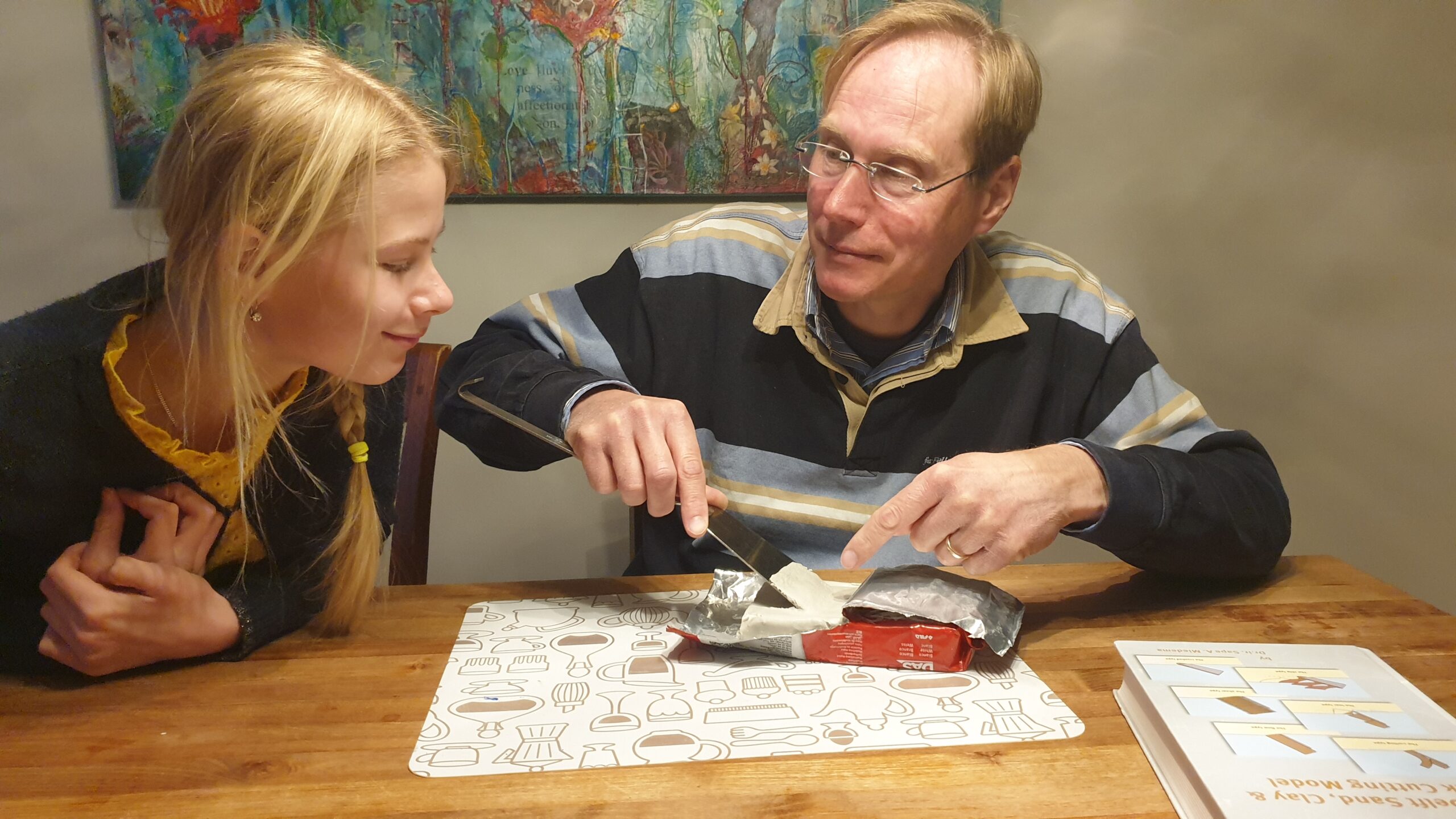
You may already know, that I am very interested in this miniscule particle that is the foundation of our business. To learn more about this element, I joint the Working Group ‘Sand’ of the Dutch Association for Geological Activities1. It is a colourful group of enthusiasts that collect, photograph and research sand in all its splendour. During the relaxed Saturday afternoon meetings, the members gradually noticed, I had a slightly different, professional interest in sand. They boldly asked if they could visit our company for their annual excursion. Maybe my presentation, by at least the excellent weather made for a very successful event.

One aspect of the sand grains we wanted to measure was the buoyancy of the particles. This is done by measuring the density of the grains. You have a tube of water with a known volume. You add sand with a known mass. And just as Archimedes2 predicted, the water will rise with the displaced volume of the grains. Dividing the mass by the displaced volume yields the density of the grains. Surprisingly, this method is quite accurate. For a static condition this is perfectly satisfying. However, in most dredging situations, the grains are dynamically jostled around in slurry transport or breaking up sediment at the cutter.
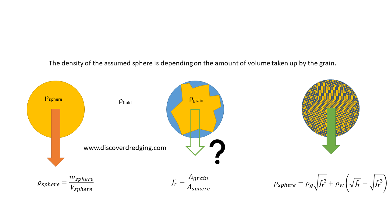
When a solid grain is moving through a fluid, it is usually considered as a perfect sphere. Nothing is perfect in nature and grains do have a range of shapes, that at best are similar to potato’s. A very jagged grain will have lot’s of nooks and crannies filled with the fluid. This fluid is moving with the particle and contributes to the mass and volume of the particle. This adherent fluid is much more reliably assumed to be a sphere. Fluids in a zero gravity situation tends to behave like a sphere. The diameter of the sphere can be taken as the maximum diameter of the grain that can be measured.

Through a microscope, you will only be able to see the lateral area or the cross-section of a grain. Both area and volume have a relation to diameter. So, the measured area is reduced to an equivalent round area with an equivalent diameter and consequently an equivalent volume. The volumes and masses of that equivalent volume of sand and the shell of adherent water will yield an apparent density of the moving particle.

In the end, my objective was to learn through the microscope the effect the shape of the sand had on the performance of our dredges. As seen in a calculation in our production estimating program, the effect can be significant. Certainly an influence we want to know and assist our customer with appropriate advise3. My visits to the meetings of the Working Group ‘Sand’ were a real benefit in understanding sand. But, to my surprise, through the working group I also learned to appreciate the beauty of the all the different sand minerals that can be found.

References
- Werkgroep Zand, Stichting GEA
- Archimedes, Wikipedia
- In house R&D Department, Damen Dredging Equipment