Graduation Fabian Kruis: Modelling Friction In Clay

Fabian Kruis presenting his graduation research

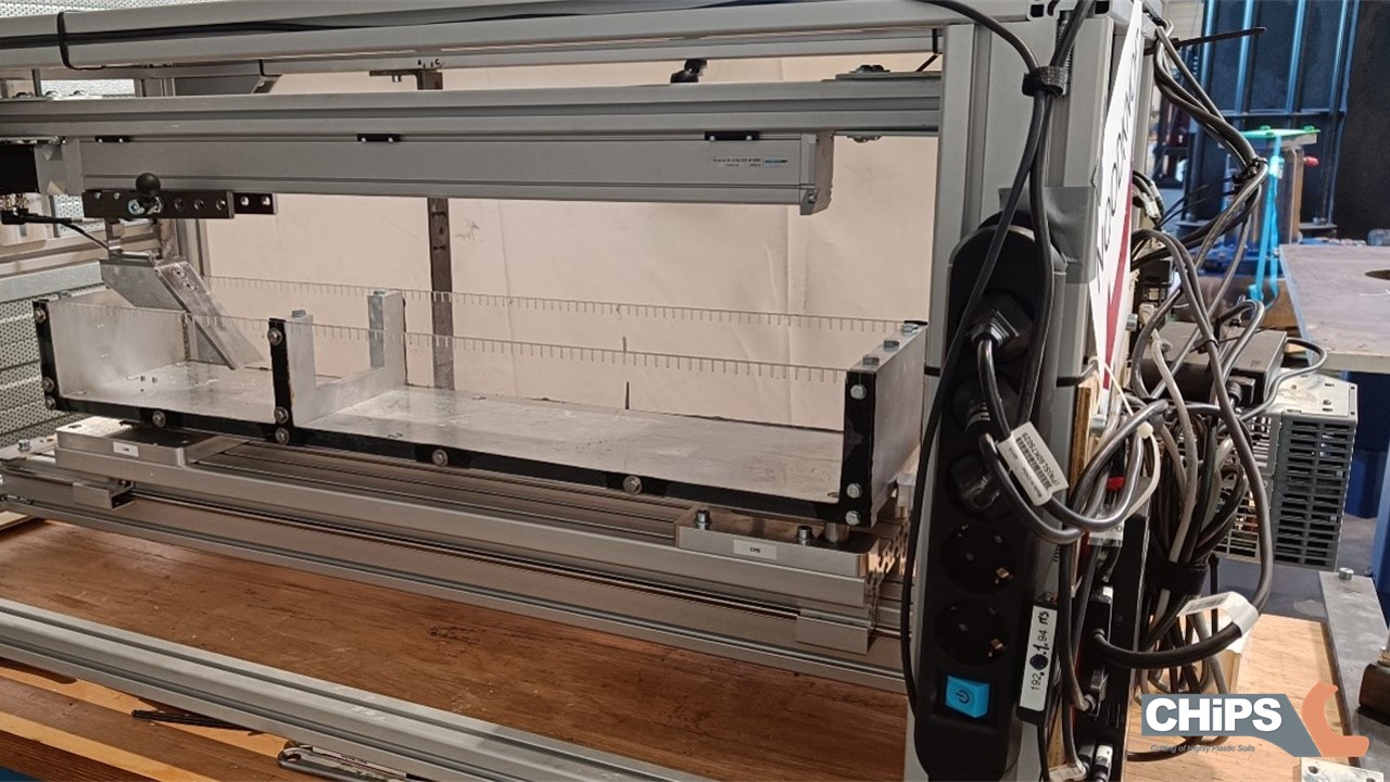
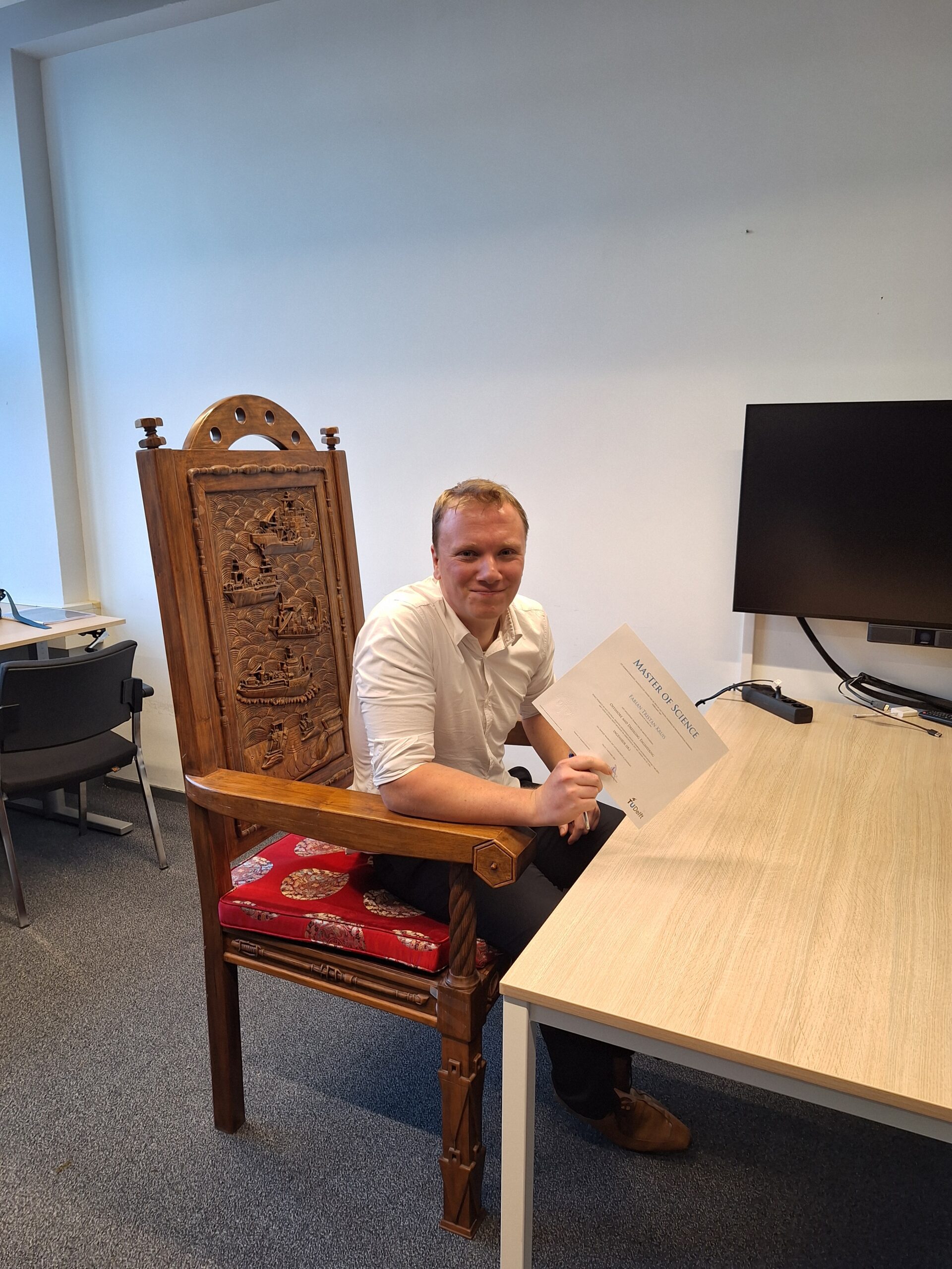
Fabian Kruis graduated on his master thesis at the Delft University of Technology on a project for my PhD research1. He investigated the cutting behaviour of plastic clay. As it was the first time we are now actually using the test rig designed by Ines2, he first had to do was a lot of trouble shooting for commissioning the test rig. Spoiler alert: the cutting forces were much higher than expected and the linear drive was not strong enough to cover the whole range of experiments we’ve wanted to do.

Clay cutting test rig at DDE in Nijkerk

The cutting forces involved with cutting of clay are acting on all four sides of the simplified chip. On the outside, there is the barometric pressure of the surrounding water. On the far end, there is an unknown and hard to determine force from the rest of the chip that is not in contact with the blade anymore. At the shear plane, there are the normal force, the internal friction and the cohesion. At the blade, there are the normal force, the external friction force and the adhesion. The sum of these last three forces will give the cutting force we are looking for, as they make up the required cutting power on the drive. But they can only be calculated, once the other forces are known.

Overview of all the forces involved with the cutting of clay, acting on the chip

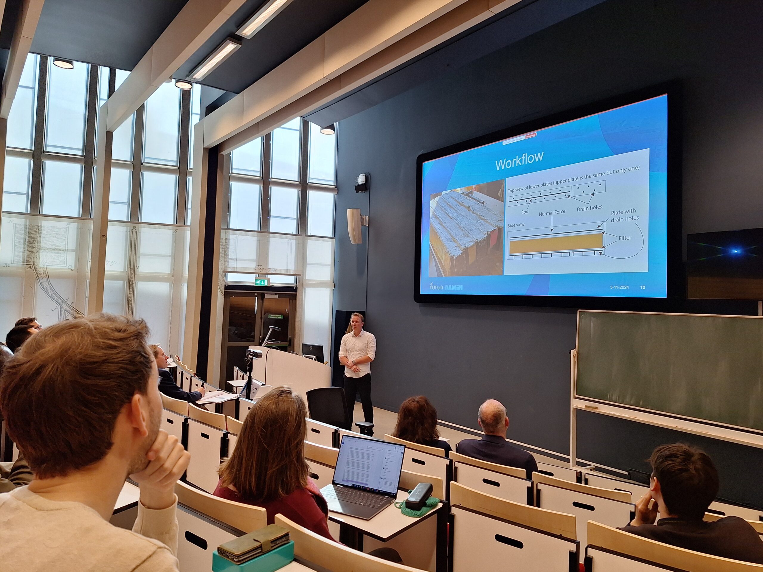
Fabian’s assignment was to have our own experience with the cutting of clay and check whether the models used in the dredging industry have any reliability in predicting the cutting forces. checking whether all assumptions and simplifications were justified. e.g. Plastic clay does have similar properties and behaviour as a fluid. And a fluid does not have an internal friction. Consequently, clay should not have an internal friction also. Right? When there is no internal friction, there can’t be an external friction either. Right, right? Fabian tested these assumptions by actually performing shear tests on internal and external planes.3

Explanation of internal friction for solids, fluids and clay

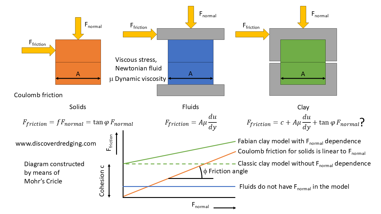
At least for the clay we used in this research, he already found that the assumption for ‘no friction in clay’ is not valid. Consequently, this had knock on effects on the rest of the cutting force calculation. We did find a different behaviour, the shear plane was off and the cutting forces were indeed much higher than expected. It is now up to me to use Fabians results and model modifications to implement into my own research. As a matter of fact, I used part of his thesis to write an article and hope to present this soon. I’ll keep you update on those developments.
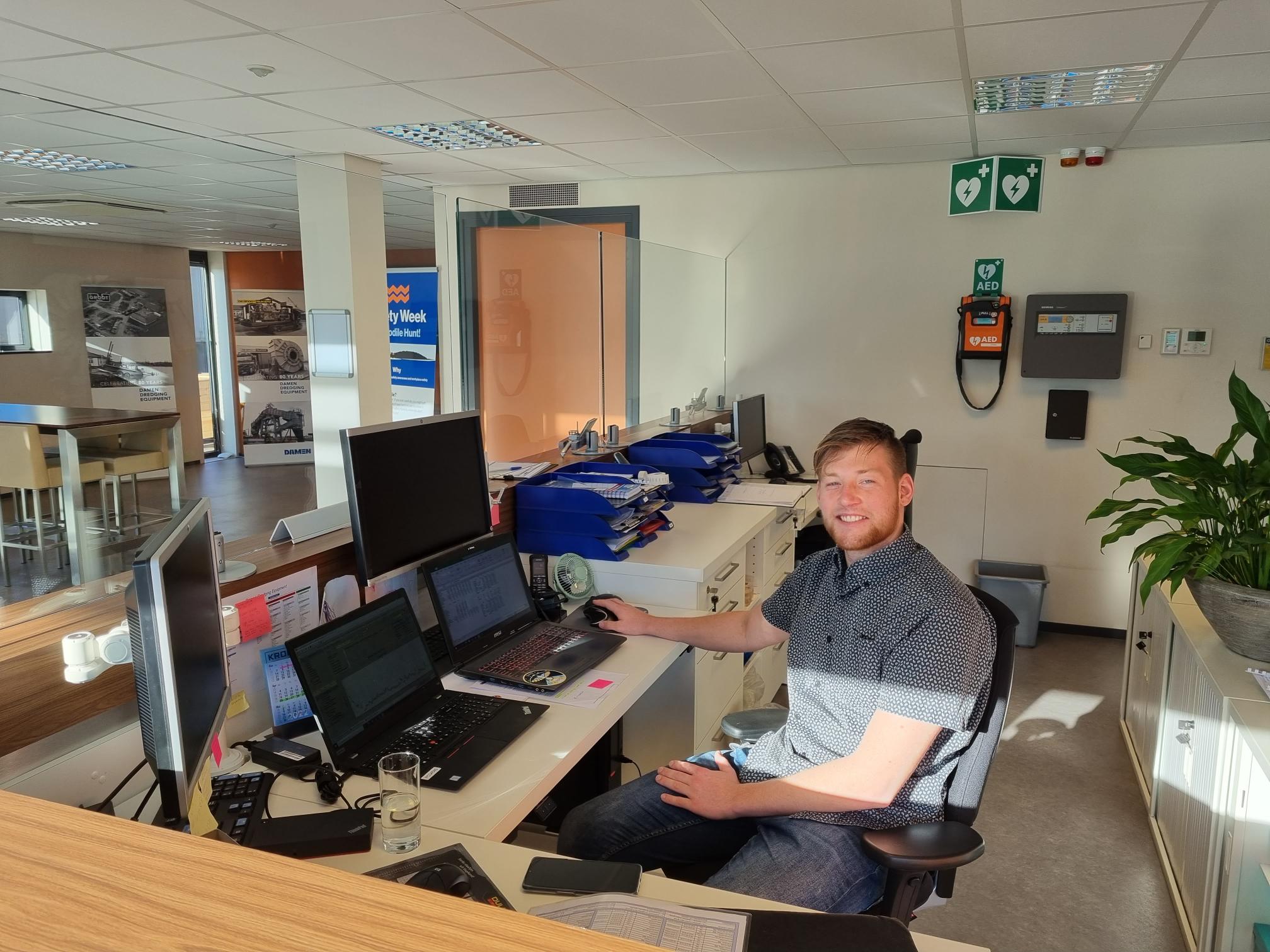
As we are very satisfied with Fabian’s work and him as a person himself, we offered him a position in our team at Damen Dredging Equipment in Nijkerk, which he happily accepted. So, next to progress for my research, we have a new colleague. Welcome Fabian, thank you!

Fabian signing his MSc. certificate.
Fabian signing his MSc. certificate sitting in the ‘dredging chair

References

  1. Personal Announcement: Going Back To School To Cut Some Clay, Discover Dredging
  2. Graduation of Ines Ben M’hamed: The Strength of Clay in a Test Rig, Discover Dredging
  3. Direct shear test, Wikipedia

See also

Graduation of Ines Ben M’hamed: The Strength of Clay in a Test Rig

Ines Ben M’hamed defending her graduation thesis

Last week, Ines Ben M’hamed graduated with good grades on her bachelor thesis. She did a project with us at the Research Department of Damen Dredging Equipment in Nijkerk. The topic was to investigate the strengthening of clay when it is subjected to shear. This deformation is a common phenomenon when cutting clay and as such a contribution to my own PhD project1 and consequently improving our products for these applications. A common problem with clay is clogging up the cutter head, but it is also not completely understood why the clay is behaving as it does and how much power is involved for the various regimes.

Fully covered cutter head in sticky clay

The effects of deformation on the behaviour of clay are much more pronounced than e.g. sand or rock. Rock does not deform, it just breaks. Sand deforms, but as it basically only involves hydraulic and mechanical forces, it is much better understood. Clay particles have wider range of interactions. Next to the hydraulic and mechanical forces, they may experience: adhesion and cohesion, molecular forces, electrostatic charges and chemical bonding in the higher temperature ranges. The general effect is that as the particles in the original situation may have a weak structure, the external disturbance causes the particles to get jostled around and all the mentioned interaction get a chance to hook on to each other.

Shear strengthening due to organising particles

The result is, that the particles get oriented and therewith a better opportunity to bond. The effect is a strengthening of the shear stress. As this strengthening is dependent on the strain rate, it is this strain rate, that is of interest for the prediction of the cutting forces. There are many publications available on what the consequences are of the strain rate on the Specific Cutting Energy. A well known model is by Sape Miedema2.

Strain Rate Effect on the Specific Cutting Energy (Credit: SA Miedema)

The trick with this model is, it depends on this strain rate effect. The sole experimental data available is by Hatamura and Chijiwa3 in 1975. They tested one type of clay on the three governing parameters: static shear strength, dynamic shear strength and the strain rate. There hasn’t been hardly any further experimental investigation into this problem. And as we regularly receive samples and soil reports that we can not test on these properties, it is also hard to predict the performance of our cutter heads. So, we decided to build our own cutting test rig.

Design of Ines’ cutting test rig

This cutting test rig resembles the specifications to the original test rig of Hatamura. This will allow us to verify the parameters in the model ourselves. We also prepared the design with various option to enable us to allow assessment of clay samples that we receive from clients and service engineers. We hope to provide our customers with additional service in this problem. Currently, the parts of the test rig arrived very late and Ines was not able to include the build in her project. Respect for the good grade she received for her thesis. However, the parts are there and provide and excellent opportunity for the next graduation student to do their project with our company. Who dares?

Available parts for the cutting test rig

References

  1. Personal Announcement: Going Back To School To Cut Some Clay, Discover Dredging
  2. The Delft Sand Clay & Rock Cutting Model, SA Miedema
  3. Analysis Of the Mechanism of Soil : 1st Report. Cutting Patterns of Soils, Hatamura & Chijiwa

See also


Graduation Of Alex De Rooij: Pumps Actually Fly Like An Unusual Airplane

Alex de Rooij receiving flowers from Suman Sapkota for his graduation

When you hire a carpenter, he repairs everything with a hammer. So, what happens when you ask an aeronautical student to solve some issues in a dredge pump? He models the pump as a badly behaving airplane. And with success, Alex de Rooij joined our company as a graduation student and recently graduated on the topic of ‘Numerical Study on NACA Profiles Sensitivity in Dredge Pump Impellers’.

The normal procedure for designing pumps is relatively straight forward. Set the performance specifications and try to hit that mark with the simulated behaviour from an iteratively improved design. This is well documented and I’ve been writing about this process before.1

Pump design workflow (inspired by Suman Sapkota)

One of the design parameters is the NPSHr. This is basically the amount of absolute pre-pressure the pump requires to operate.2 The system and operating conditions will result in a certain available pre-pressure: NPSHa. When the NPSHa drops below the NPSHr, the pump will experience cavitation at the low pressure side of the blade. The flow of the medium will be disturbed and the performance of the pump will abruptly crash. There is some warning. Operating near the NPSHr, there will be an incipient cavitation where the vapour bubbles start to form, but do not cause any issue. The imploding vapour bubbles may be detected audibly for the trained listener.3 Next will be a stage on the NPSHr, where the bubbles get larger and they loudly implode. At this stage, the pump sounds like it is tumbling nuts and bolts inside. These imploding bubbles will definitely cause damage to the impeller. At last, working below the NPSHr, the bubbles will become so large, they will block the passage between the blades. The result is an immediate drop in delivered head.

Explanation of NSPHr, NPSHa and cavitation

The flow of the medium through the impeller can be simulated in a CFD program. Specifically for impellers, you will need to model a rotating frame of reference. And that is the usual representation of the results. However, with mathematics being one of the most powerful tools invented by humanity, we can have an alternative view on these results. We can cut the impeller along a radial and stretch open the meridional passage and the blades to a row of foils. And that is exactly where our young aspiring engineer comes in. In literature, the blades in the impeller are modelled having a constant thickness. But, Alex has been investigating what the influence will be when we model the blades as foils. Selecting a proper profile makes the blade less sensitive to stalling.

Conversion of axial view to blade to blade view

Alex, thank you very much for your work here at Damen. We’ve learned the influence of certain profiles on the performance and geometry of the pumps. You have the right mindset to pass your time at the TU Delft and graduate successfully over there also. And whenever you have some days of the month left after you spend your allowance, know that we can give you a warm reception at our office.

Alex working at the reception desk at Damen Dredging Equipment

References

  1. Our Interview About New Pump Designs In The Latest Damen Nieuws, Discover Dredging
  2. When does your pump suck? Discover Dredging
  3. Cavitation in a Water Pump and Valve, Mountain States Engineering and Controls

See also