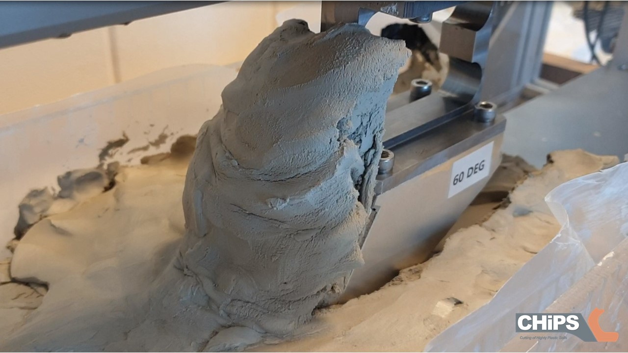
Prasanna Ramadurai has been doing an internship with us at Damen Dredging Equipment for my PhD project on the cutting of clay1. As an old fashioned analytical and experimental dinosaur, I have been working in my comfort zone. However, when submitting articles the response from the reviewers has been: ‘How about validating your results with a numerical simulation?’ And that is exactly what Prasanna has been doing for me these months. Now he has presented his work and I can use the results in my own research.
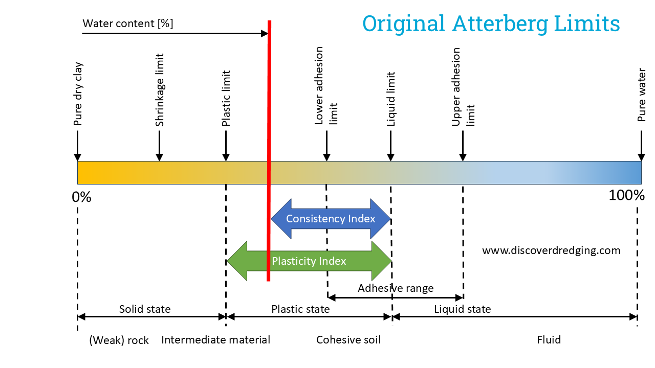
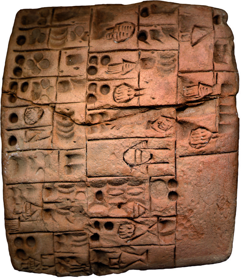
Clay is a strange material. It is neither a solid, nor a fluid. Depending on the amount of water in the material, it can behave like concrete or like water. The scale on which this can be described is defined by the Atterberg limits2. Well known soil parameters as Plasticity Index and Consistency Index are derived from those Atterberg limits. Atterberg himself defined the following limits:
| ID | Limit name | Criteria |
| 1 | Upper liquid limit | Starts to show signs of a viscous fluid |
| 2 | Lower liquid limit | Normal Casagrande test or Fall cone test |
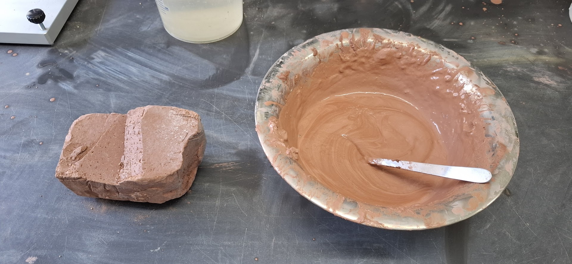
| 3 | Adhesion limit | When no clay sticks to a nickel spatula |
| 4 | Upper plastic limit | Can be moulded |
| 5 | Lower plastic limit | Normal rolling test for plastic limit* |
| 6 | Cohesion limit | When pieces of clay do not stick to each other anymore |
| 7 | Shrink limit | Normal shrink limit, constant volume for water content |
| *Atterberg proposed to roll on a paper surface, whereas ISO 17892 proposes a glass plate | ||
The consistency limits as originally proposed by Atterberg
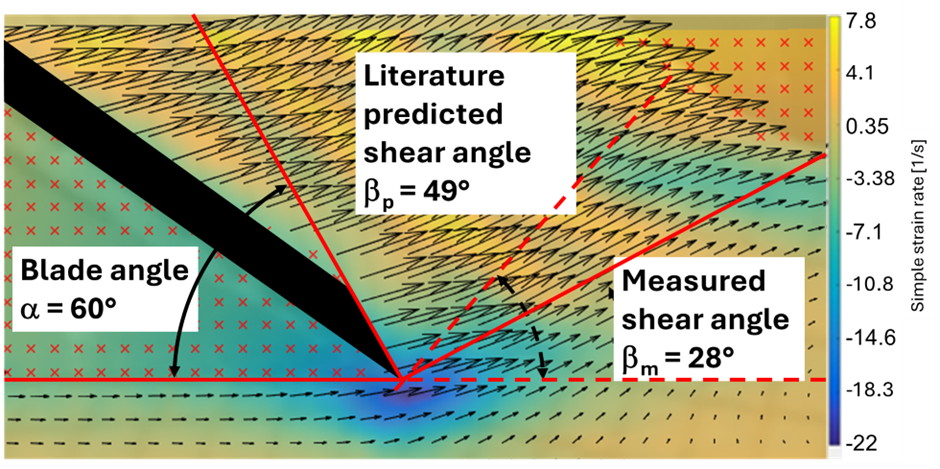
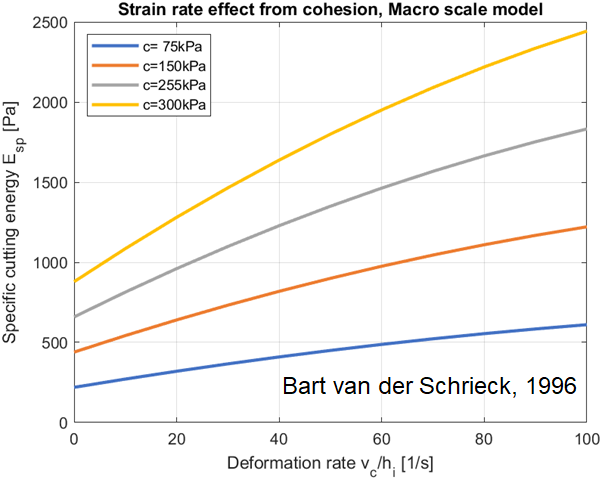
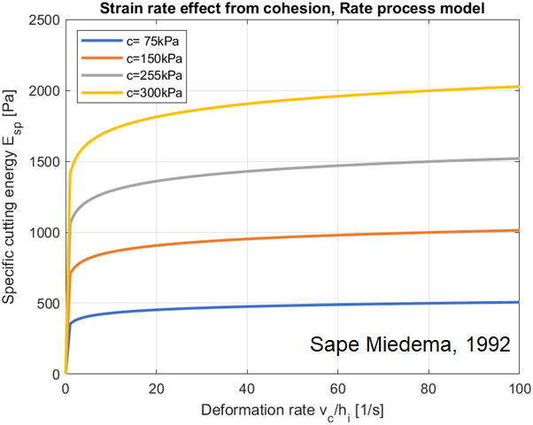
The resistance of a material to deformation can be expressed as the resulting stress due to a strain rate. When there is immediate stress for even the slightest movement and constant after reaching a yield stress, this is typical of a solid. On the other hand, when a material starts to move immediately and the resistance to deformation increases with the strain rate, it is a fluid. And clay is just the typical material that exhibits both phenomena.
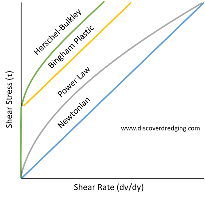
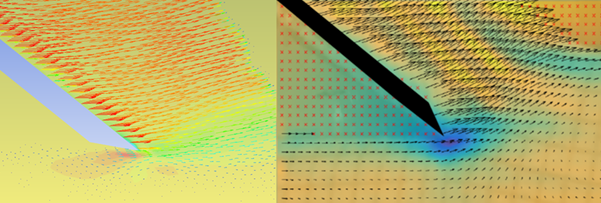
In rheology, the factor which shear stress is related to the increased strain rate is called viscosity3. However, due to the internal friction in clay, the stress follows the vertical axis and consequently, the viscosity becomes infinite. Prasanna squeezed out the capabilities of the CFD program using some clever mathematical tricks of a Herschel-Bulkley fluid model to get the simulation to behave. And the results are promising enough to follow up in a separate study.
For supervising Prasanna, I am very grateful for the assistance of Suman Sapkota for his knowledge of computational fluid dynamics. Together with my knowledge of clay, Prasanna gained a very special set of skills in this area. Prasanna will be back at the TU Delft to continue his master’s graduation project. I can recommend him for having him in your team.