Young CEDA Evening: the Grabbing History of Dredging

Presenting my lecture on the history of dredging at Young CEDA

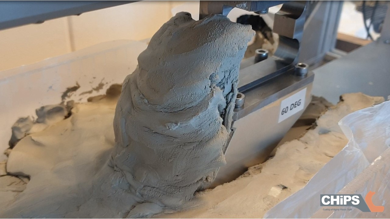
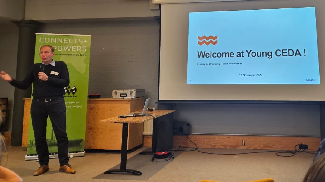
Last Tuesday, I gave a presentation for Young CEDA1. The topic was to be about the history of dredging2. And I happily accepted the invitation to educate the younger generation into the tradition of our craft. I consider myself somewhere in between. Not part of the old generation, but past the younger generation. Though I am old enough to have heard the old guys talk about their history and their knowledge of where our modern industry came from. In particular those stories came from the lectures by professor Jan de Koning3 I attended as a student. He really was able to put a perspective on the origins of processes and technologies. Some of those stories have been recounted on my website already4. The oldest dredging project5, the oldest rock cutting technology6 and the oldest dredge canal7 still in use. They were all there at the presentation that evening.

Traditional dredge scoops for peat dredging and waterway maintenance (Credit: Wikipedia)

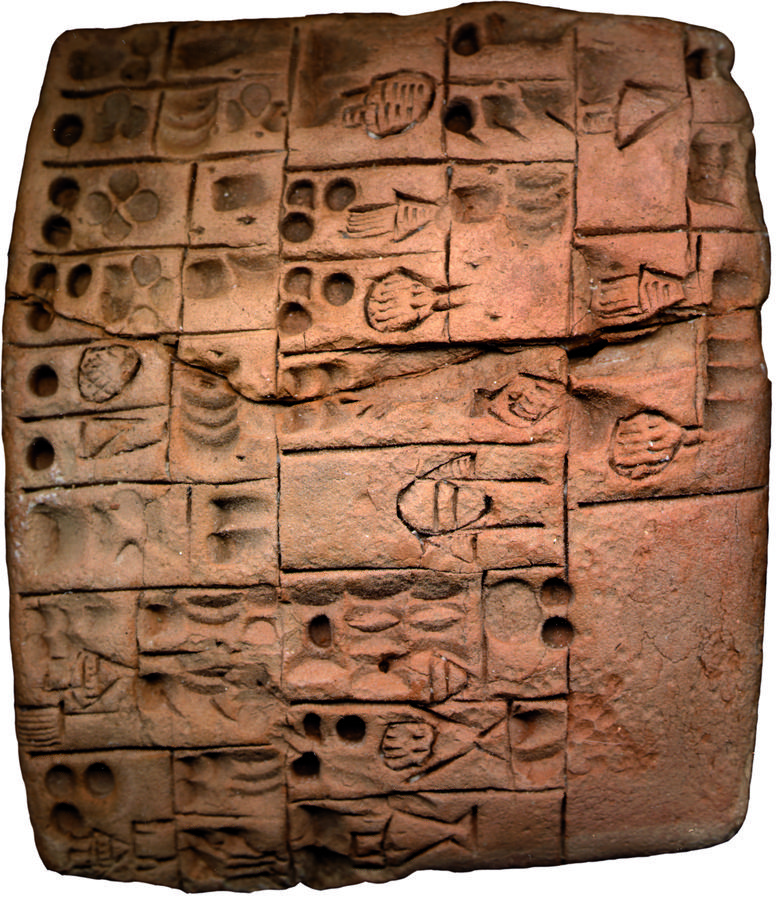
Here I would like to focus on another development presented that evening, but new on my website. A well known tool in the industry was the dredge scoop8. It has been used for ages, until even recently. However, the working depth is limited to the length of the stick. Longer would make it hard and impractical to use efficiently. In ancient Persia, there were three Banū Mūsā brothers9. Three scholars in 9th century Baghdad, who worked on astronomy, mathematics and engineering. Ahmad Banū Mūsā published ‘The Book of Ingenious Devices’10 which described a tool to pick things up from underwater, specifically oysters.

Oyster grab invented by Ahmed Banu Musa (Credit: 1001 Inventions)

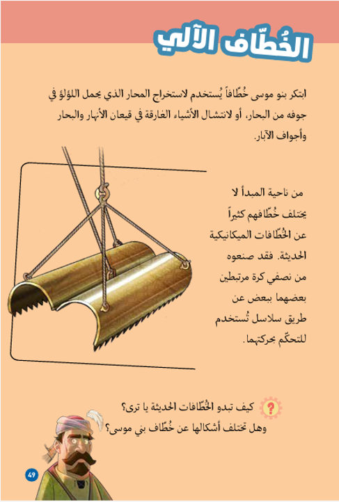
Ahmed Banū Mūsā described in detail the phases in the cycle: lowering, closing, lifting and opening. And it already looks very familiar to the grabs we are using today in the dredging industry known as a clam shell grab. Modern versions are constructed from steel and hydraulically operated. The capacity is usually a couple of cubic meters. But there are designs of up to 200 cubic meters11. The advantage of grab cranes is their simplicity and employability. Whether sand, clay or rock, special versions can adapt a crane to the requirements of your project. The disadvantage is that they can be messy and it is a discontinuous process. Usually involving multiple barges, making them labour intensive. Still, with the right experience and man power, this is the tool of choice for many countries.

Closing process of a clam shell grab under water (Credit: Sape Miedema)

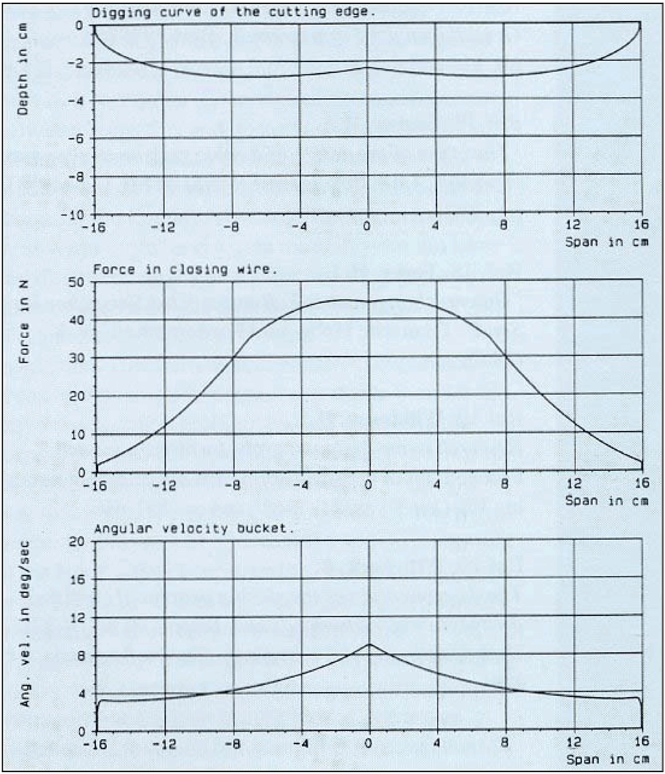
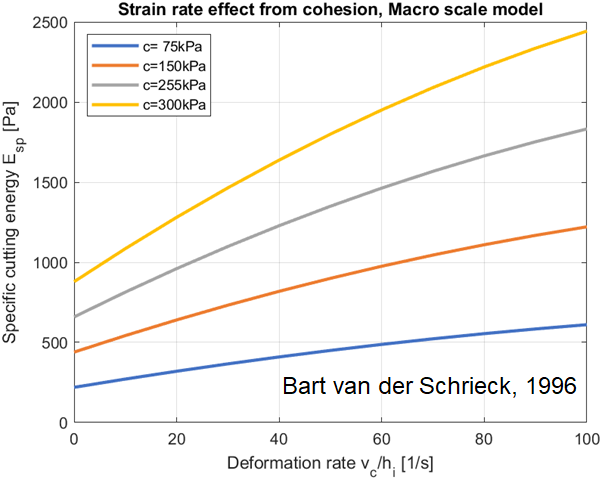
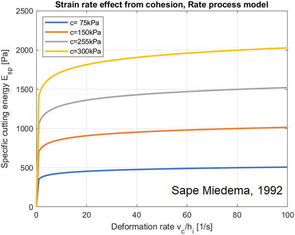
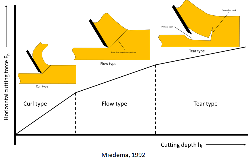
One of the most important phases is the closing process of the clam shell grab. Here are the limitations on the power and operating speed, that are the most important in the calculation of the cycle time and equipment capacity. Sape Miedema has proposed a model for this phase in the grab cycle12. The rest of the cycle is just adding up the operating times and multiplying by your number of cycles.
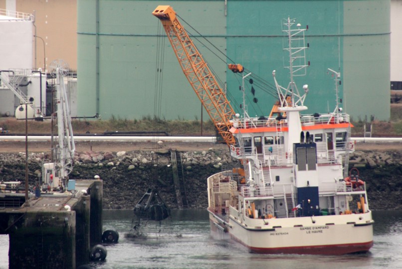
Sometimes the grab crane is placed on the barge itself to reduce the total investment and running costs. When looking for such a vessel, it can also be interesting to consider adding a trailing suction pipe or a DOP pump to make the vessel even more adaptable to the project requirements.

Damen clam shell grab crane hopper with a trailing suction pipe

References

  1. Young CEDA, CEDA
  2. Young CEDA, CEDA-BE & CEDA-NL Event, CEDA
  3. Tag: De Koning, Discover Dredging
  4. Category: History, Discover Dredging
  5. The Ancient History of the Cutter Suction Dredge ‘10th of Ramadan’, Discover Dredging
  6. Graduation Omar Karam: Rock Cutting The Egyptian Way, Discover Dredging
  7. Historical Origins Exhibition at the WODCON: the Beijing-Hangzhou Grand Canal, Discover Dredging
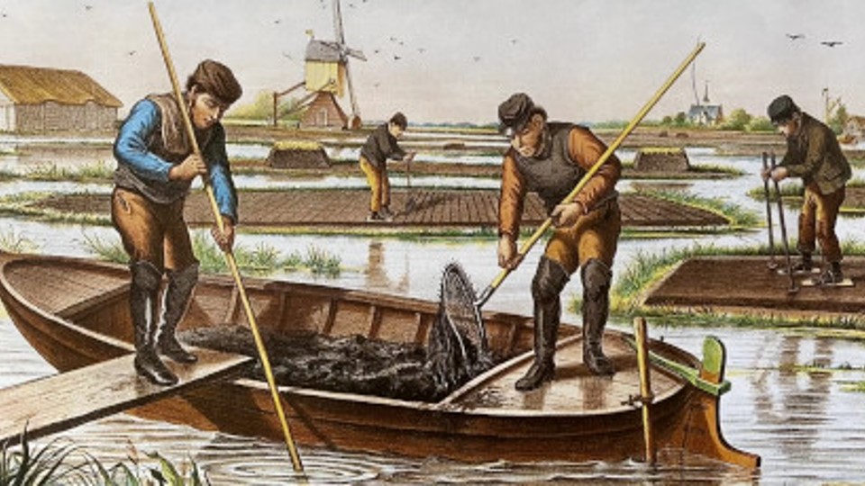
  8. Paying Tribute to the Hard Life of Peat Dredgers, Discover Dredging
  9. Banū Mūsā brothers, Wikipedia
  10. Book of Ingenious Devices, Wikipedia
  11. Tosho, DredgePoint
  12. The Closing Process of Clamshell Dredges in Water-Saturated Sand, WODCON

See also

CEDA Industry News: Snap Back Story out of the Old Stone Box

Cutter wheel dredge ‘Sylvia’ at work on the TIWAG Langkampfen power dam reservoir

You might have read the CEDA Industry News1 publication of September and the LinkedIn announcement2. Or, have been present at Session 10, The Story of Safety3 of the CEDA Dredging Days 2024, where I initially recounted my story of misfortune. For the uninitiated, I’ll shortly recount it over here, although the focus will be more on the design problem back than.

Me telling this story at the Safety Session of the CEDA Dredging Days 2024 (Credit: CEDA)

When I was fresh out of university, working for my previous employer, I was assigned to advise during the commissioning of a bucket wheel dredge in Austria. Here at my website, I’ve already mentioned a very peculiar problem we had with starting the dredge on Monday morning4. The whole dredge was a funny contraption, trying to fulfil the specific requirements set by the customer. The task of the dredge was to clean out the sediment caught in a silt trap5 in front of a power dam to prevent the material flushing through the delicate turbines. Furthermore, the fine sediment should be removed from the system to be sold for beneficial use, but the larger boulders that came along should be rejected from the system. Unless they were very large and stay in place for forming the liner of the silt trap.

General modes of siltation at the usual location in a reservoir

The proposed method was to use a bucket wheel to gobble up the larger stones, but leave the even bigger ones down at the pit floor. Additional advantage of the bucket wheel is that they tend to have a very low resuspension rate which is beneficial for reducing the turbidity in the river and save the dam turbines. However, the larger stones taken by the bucket wheel will not pass the dredge pump. A proven solution to filter out stones for the dredge pump is a so called stone collection box. They come in various executions, but this one was a large cylindrical vessel with a cover on top. Inside was a cage that connected to the inlet and outlet of the vessel. When the cage was filled, the lid was lifted by the crane and the attached cage came out. The cage was swung over to a barge alongside and the stones were unloaded through a trap door. Sounds straightforward, right?

General arrangement of the ladder and suction system on bucket wheel dredge ‘Sylvia’

The thing is, when you have anything in the suction pipe section, it will create a pressure loss and the pressure in front of the dredge pump becomes lower. Or higher vacuum, as you wish. This is already a problem for an inboard pump when you are working at sea level, even more so when working at altitude. The NPSHr is easily reached. In order to have enough NPSHa, even when the stone collecting box was filling up, it was decided to have a submerged dredge pump for increasing the pre-pressure. Consequently, the stone collecting box would also be placed on the ladder, in front of the dredge pump.

Explanation on NPSHr and NPSHa in mountains and submerged, including stone box

All in itself no problem. The disadvantage is that a submerged stone collecting box should be very strong, big and heavy to withstand the under pressure, although there is very little room around the ladder, the ladder itself becomes quite heavy and bulky and the submerged frontal area increased dramatically, increasing the total drag of the dredge in the fast flowing river current. To mitigate this, the ladder winch, the service crane and the 25 ton forward wire winch were all stacked over each other, so each could do it’s job independently. Although none of us ever did a collision check in the design phase of the dredge. In actual operation, they all were in each others way. When lifting the cover of the stone collecting box, it got caught by the forward wire. When lifting it further, it slipped of the side by the strong drag forces on the wire. I was to first to experience our negligence and got hit on my head when I was to eager to inspect the contents of the box. I blacked out, fell in the frigid water in the ladder well and woke up washed up on the ladder. My colleagues rushed me to the hospital, where I ended up between all sorts of winter sports injuries. Fortunately for me, I am able to recount my story and share it here and through the CEDA Industry News.

Annotated overview of the accident site where the wire slipped from the cover onto my head.

References

  1. Dredging safety under the spotlight, CEDA
  2. Safety is paramount, CEDA
  3. Welcome to CEDA’s (revamped) Dredging Days 2024
  4. The Dredge That Refused to Work on Monday Morning
  5. A Reservoir of Dredging Opportunities

See also

CEDA Dredging Days 2024: My Presentation On Clay Cutting

Initial clay cutting tests for my PhD project CHiPS

Next week is the biannual CEDA Dredging Days event1. This time fully focused on presentations, networking and having a good time together with like minded people. Since a long time, it will not be in conjunction with the distractions of the Europort exhibition. Instead, it will be in the impressive WTC Rotterdam. This is an excellent opportunity to share with you the progress of my PhD project on clay cutting at the TU Delft2. As a teaser, I would like to share with you some observations from my literature study, already3. Starting to search for literature via Google results in this:

Literature on clay (Kushim, 3400BC)4

When estimating the cutting production of a dredge, the objective is to find the specific cutting energy for that dredge in combination with the soil properties and correctly chosen operational settings. The specific cutting energy is the amount of power needed to excavate a volume of soil from the bottom5. The funny thing is, when you work out the dimensions of the specific cutting energy, the unit is similar to a stress or pressure. So, there should be a direct relation between the specific cutting energy and a soil property. But which one? For cohesive soils as clay, there are: shear strength, cohesion, adhesion, tensile strength, yield strength. The VOUB course6 recommends to use an empirically derived relation between the cohesion and the deformation rate (which in turn is based on the operating settings) for the specific cutting energy.

Specific Cutting Energy Empirical (Bart van der Schrieck, 1996)

In contrast to this empirical model, one could also start at the displacements of the clay particles and model the implications for the larger continuum mathematically. This has been investigated by Sape Miedema, who has published countless articles and an impressive book on the topic7. Following this through, the estimated specific cutting energy is in the same range as the empirical model. However, on closer inspection, there are some variations on the outer limits of the deformation rate.

Specific Cutting Energy Theoretical (Sape Miedema, 1992)

This discrepancy is probably due applying the model under all conditions. Miedema already recommends to check for the validity of the assumptions in the model. At very thin cutting layers, the resulting chip may form a long curl. When cutting thick layers, the blade will cut out chunks. And those cutting types will have different force equilibriums, resulting in different cutting forces. Miedema suggested a three regime map of cutting types, which coincidently resembles the curves found empirically.

Cutting types (Sape Miedema, 1992)

It appears, there are many more cutting types possible for a myriad of soil properties and operating conditions. However, the published results and proposed models are not directly applicable for the dredging industry. Either the conditions or assumptions differ (dry earth works for example) or parameters or data has been failed to included in the publication. This leads to some white spots in the knowledge that I hope to colour in with my future models and upcoming experiments8.

Clay cutting test rig at DDE in Nijkerk

References

  1. Welcome to CEDA’s (revamped) Dredging Days 2024
  2. Personal Announcement: Going Back To School To Cut Some Clay
  3. CEDA Announcement of my presentation, LinkedIn
  4. What was the first (known) maths mistake? Matt Parker
  5. Experiencing The Cutting Edge Of Dredging Technology
  6. VOUB Cursus 1998, Deel X, hoofdstuk 12, VBKO
  7. The Delft Sand, Clay & Rock Cutting Model, Sape Miedema
  8. Mechanical excavation of clayey soils, a review of the physical phenomena occurring, Mark Winkelman et al (CEDA Dredging Days 2024)

See also