Sensible Flow Sensing Stories, The Correct Capacity Measurement

Example of a flow meter on a Cutter Suction Dredge

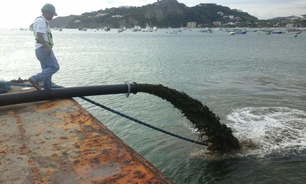
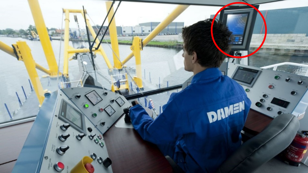
My last posting was a nice story about how they measured mixture velocity in the old days1. Luckily, we have a much better solution nowadays: the electromagnetic flux flow meter2. It is real time and can be viewed from the convenience of the operating cabin. This device can be part of the production measurement for a CSD, TSHD or sometimes in a separate production measurement unit.

Combined velocity and density indicator in the operating cabin

The working principle of an electromagnetic flux flow meter is based on the Faraday laws of induction3. When a conductor moves through a magnetic field, a current will flow in the third direction perpendicular to both. Due to the resistance of the water, the resulting potential can be picked up by electrodes that are in contact with the mixture.

Explanation of the electromagnetic flux flow meter

For the principle to work, the electrodes and the mixture have to be isolated from the housing. This is why you always have some isolating liner in this type of flow meters. Off course, the isolation material will wear down due to the abrasion of the mixture. Usually when working in relatively soft sediments, the isolation liner is made of durable polyurethane rubber. The electrodes are flush with the surface of the liner and are not much exposed to wear. When the liner is worn down, it can be easily replaced by the supplier. When working in a more abrasive environment, a more durable isolation liner can be chosen. e.g. Ceramic tiles embedded in a soft adhesive layer.

Arrangement of an electromagnetic flux flow meter

The measured voltage gets processed by an amplifier that has to be placed close by. The outgoing signal is mostly the usual 4-20mA and can be transmitted directly to a velocity indicator or a production indicator. Sure, it is good to have a high velocity, as that represents a good production. But it is also indicating a high power consumption. One is more sensible to increase the mixture density and decrease the velocity for an efficient production. To monitor the dredge process, both signals can be combined in a single indicator to present the production to the operator.

Example of different executions of production indicators

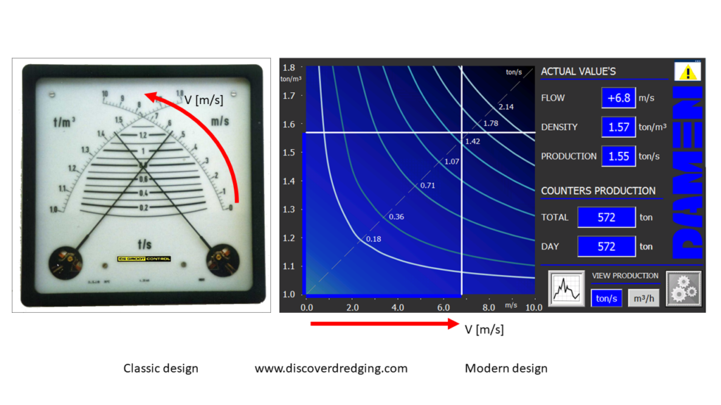
The left example is the classic ‘mechanical’ cross-needle indicator. Where the needles intersect, the production can be read on the lines between the scales. On the right, the rotating needles have been replaced by digital linear scales. The velocity is represented horizontally and the density vertically. Consequently, the production lines are also modified. Instead of a high production vertically in the centre, the highest production is now in the upper right corner.

These flow sensors are quite accurate and are reliably indicating the correct value. Still, it is good practice to check the indicated flows, after installation. This calibration can be done for one or two points. The easiest check point is with static water. The other point will be with some known flow. If the installation is on a TSHD, it is straightforward to fill the hopper. Be aware, that the flow has to be integrated over the filling time. For a CSD type application we may have to resort to the described end of pipe indicator from previous post. And if the values are off, erratic or otherwise not making sense, you might have to check whether the housing of the sensor is correctly grounded to both other flanges.

Ungrounded and correctly grounded housing of a flow sensor

References

  1. Increase Your Dredging Knowledge At The End Of The Discharge Line, Discover Dredging
  2. Magnetic flow meter, Wikipedia
  3. Faraday’s law of induction, Wikipedia

See also

Increase Your Dredging Knowledge At The End Of The Discharge Line

Keeping watch at the end of the discharge pipe line

Solving something at the end of the pipe is usually a less desired approach. However, in dredging, it is the place where the valuable stuff is delivered, it might be a good place to start monitoring your process. Let me explain this to you by going back to latest discussed exhibit at the Damen Dredging Experience1.

Pump power exhibit at the Damen Dredging Experience

You might have observed in the pictures of the pump power exhibit, that the velocity of the water flow is indicated by the parabolas of the trajectory. The arc of water is bound by gravity and obeys this trajectory always; independent of the density of the mixture. The two equations of motion can be combined, where the time parameter falls away and the height for a certain distance is only depending on the initial horizontal velocity2. As such, it is fairly accurate indication of the pipe flow. The calculation is universally applicable on earth and the results can be presented in a very simple graph to take with you. Every parabola is labelled with the corresponding horizontal velocity.

Nomogram to find end of pipe velocity

The above example is a straightforward method to measure the mixture velocity. The US Geological Survey even extended this approach as a standard method to measure the production of wells3. The resulting nomogram has a slightly different layout, as it is intended for finding the production instead of the velocity. For production planning, this will be useful. For monitoring your dredging process, the velocity might be more important. Both approaches of this elegant method do have the benefit, that there is no obstruction needed as in the case of an orifice measurement4.

Nomogram to find the end of pipe production

There is an unconfirmed anecdote that my old professor de Koning started his career as a velocity measurer. In the old days, when he was working as a twelve year old boy with the dredging company of his father. He was assigned to keep watch at the end of the pipe and monitor the mixture pouring out. He had a simple beam with a plumb bob. The beam was moved along the top of the pipe, until the plumb bob was touching the arc of mixture. On the beam were two markings. When the beam was moved in and passed the first mark, the mixture velocity was too low and a red warning flag had to be displayed. If the beam had to move out and the mixture velocity was too high at the second mark, a green flag had to be flown. There was also another white flag, in case only water came on the reclamation area. With this very simple setup, the dredge master could check through his binoculars what the state of the dredging process was.

Working principle and explanation of end of pipe meter

They were clever in those days. But the physics still apply. So, even today, one might have a situation, where there is no electronic velocity measurement available (broken, not supplied, not (yet) purchased) and you have to push the limits of the operating envelope of the dredging process. Then, there is probably always somebody around that might be appointed volunteer to be head of the velocity measurement crew. Who knows, he might have a bright future in the dredging academia.

Professor de Koning of the dredging chair at the TU Delft (1981-1993)

References

  1. Presenting Pump Power Peculiarities, Playing With Pumps And Pipes, Discover Dredging
  2. Projectile motion, Wikipedia
  3. Estimating discharge from a pumped well by use of the trajectory free-fall or jet-flow method, US Geological Survey
  4. ISO 5167 Measurement of fluid flow by means of pressure differential devices inserted in circular cross-section conduits running full, ISO

See also