CEDA DMC Visits the Anse du Portier Project in Monaco

CEDA Dredging Management Commission at a site visit in Monaco. (Credit: CEDA)

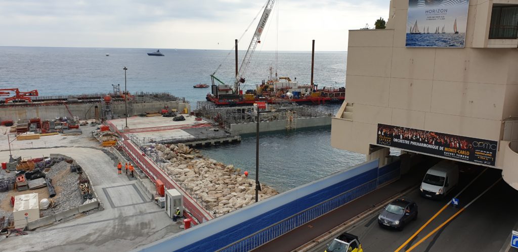
In the past intermezzo, a lot of blog ideas past my mind. In due time, I will share some of them with you. Others already arrive by themselves naturally. e.g. Lately we’ve had another CEDA Dredging Management Commission meeting1. In preparation for the upcoming CEDA Dredging Days2, we discussed some publications that will be presented there3. Next to the meeting, we also did a site visit to a prestigious project. The Monaco extension project ‘Anse du Portier’ certainly demanded some serious management skills for the dredging works.

Overview of the Anse du Portier project

The extension project had already received a lot of attention in the press and in the dredging community. It certainly is a remarkable project, where a lot of disciplines are coming together. I would like to refer you from the excellent video on the Anse du Portier project itself4:

Extension en mer de Monaco – Techniques de construction (Credit: Anse du Portier Project)
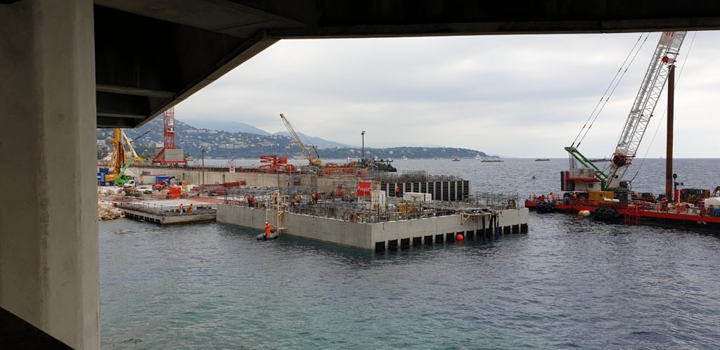
Or, if you can hold your breath, to the presentation of Camille Kapella at the CEDA Dredging Days5, where she will elaborate on all the difficult challenges in the project. At the moment of our visit, the last caisson had just been placed in the construction6.

Last caisson in the constructed sea wall at Monaco

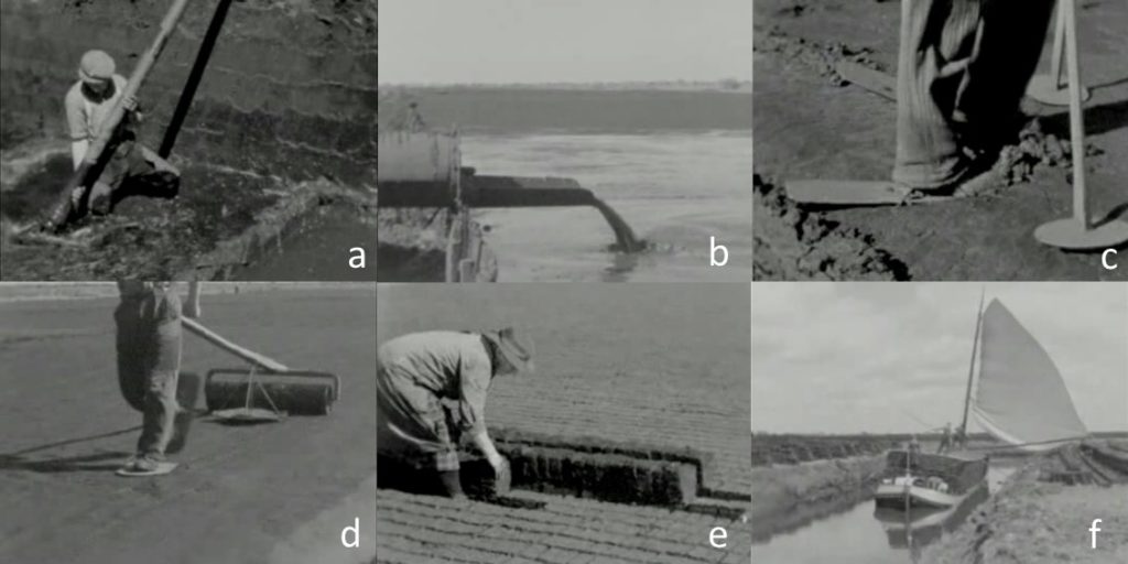
Caissons are a demanding construction in terms of dredging. Of course, there are examples, where location and placement were not so important, but usually the requirements are much stricter and the conditions much harsher. Caissons have to be placed next to each other in the first place. And joining them all together might end up in a big deviation as errors propagate through each misplacement. This has been recognised already for a long time. Even one of the first tunnels built of sunken caissons, the Maastunnel7, had specifications that are still in use today. So, how did they do this? There is a nice historic video available from the old Polygoon Journaal.

Building of the Maas Tunnel (Credit Polygoon Journaal)
In the case of the Maastunnel, they employed wires driving huge dials and sight line beacons. Under perfect conditions, enough time and an enormous amount of manpower, the objectives can be achieved. Nowadays, this approach would be too costly or can’t be used as the local circumstances prevent them. Waves, tides, difficult location or other factors are the edges of the envelope for modern caisson placement and all were present here in Monaco. Specifically, the challenges at the Anse du Portier site were the steep bedrock, the open coastline vulnerable to waves and environmental concerns. For each, of the challenges, appropriate solutions were chosen to manage the project.
The construction of the caissons to withstand the wave action during the lifetime is remarkable. The top of the caissons are equipped with so called patented Jarlan chambers8. This is a design concept known in the offshore construction to temper the wave action. Waves enter the construction through slots in the walls and enter a chamber with more columns for further dissipation of the wave energy. A similar approach is already discovered by nature itself: coastal mangrove forests.

Last caisson at the Anse du Portier with Jarlan chamber slots covered for transport

References

  1. Dredging Management Commission discusses papers on contract-type selection and soil investigations, CEDA
  2. CEDA Dredging Days 2019, CEDA
  3. Effective contract selection: CEDA’s guide to optimised contracting methods, CEDA
  4. Anse Du Portier, Youtube
  5. Dredging in Monaco: challenges and solutions, CEDA
  6. Monaco Land Extension Project Reaches Milestone, Caissons Belt Completed, DredgingToday
  7. Maastunnel, Wikipedia
  8. Jarlan Chamber, Espacenet

See also

Paying Tribute to the Hard Life of Peat Dredgers

Sculpture ‘Verveners’ by John Rijnen

It’s been a while since my last update. Don’t worry. All is well. The delay was due to my change in habitat. Moving can be draining attention and creativity, but can also create opportunities for exploring the new neighbourhood. And that is exactly what I will share as this first post. One of the first dredging related discoveries was a sculpture on a roundabout nearby. Probably most passers-by will not notice it or at most will be puzzled by the strange flat figures. To us, as dredging community, we immediately recognise the typical posture of manual dredging. Intrigued by the unexpected discovery of dredging art at this location, I went on an investigation on the background of this statue.

Sign at sculpture ‘Verveners’

The sign at the sculpture did reveal some details on the name, date and artist of this monument1. Obviously, the topic of this statue was a tribute to the people who have been working as peat dredgers and contributing to the wealth of the town. It is also a reference to the origin of the current geography of the municipality: lots of lakes and ponds that are a recreational area for the population and a resting place for nature, that were unbelievably all excavated manually over ages.

The most characteristic feature of the sculpture are long poles2 in combination with the posture for back breaking manual labour. The long pole has a hoop at the lower end with some kind of fishing net attached. The hoop is used to scrape sediment (in this case peat) from the bottom and collected in the pouch. Mud and peat are sticky enough to stay in the net for vertical transport, but the flexibility and openness enables easy discharge. For peat dredging the material was scooped up on shore and dried3. For maintenance dredging, the material was brought on board and discharged at a convenient disposal location4. The Dutch dredging industry cherishes this and remembers it with all kinds of small statues found in many offices.

Paper weights about manual dredging with a ‘baggerbeugel’ (Credit: Hendrik Jan de Kluiver)

Manual dredging shaped much of Holland’s geography, either the canals and lakes or the reclamation of marsh into pasture land. It has been identified as a typical Dutch tradition. But is it?? Preparing this post, I’ve discovered it is not. Several references say that we did not invent the ‘baggerbeugel’2. Before we started to use it, it has been applied already for ages in East Anglia5, which had a very similar landscape. Already from the tenth century, peat has been excavated from the Fenlands and later on from the 14th century, they started manual dredging already. Only later on in the 16th century Holland started to take over this practice. And in good Dutch tradition, we refined the trade and even exported consultancy on these projects back to England!

Stills from an instructional video on peat dredging (Credit: modified from Open Beelden Project)

Peat dredging is a laborious procedure and later on, this industry was mechanised. There is a nice video explaining about peat dredging in the Netherlands. Especially the hydraulic dredging starts at 08:10 into the video. All processes in a regular dredging project are identifiable: a) dredging, b) discharge, c) bulldozering, d) compacting, e) drying and f) further transport of the merchandise.

Viewing a video is one way to experience manual dredging. In the dredging garden of the National Dredging Museum6, there is an exhibit to experience this trade first hand.

Visitors experiencing manual dredging in the National Dredging Museum

References

  1. De oude tol, Rotondekunst
  2. Baggerbeugel, Wikipedia
  3. Vervening, Wikipedia
  4. Barges, IADC
  5. A Tale of Norfolk Peat Cutting, Norfolk Tales, Myths & Beyond
  6. Bagger Praktijk Tuin, Nationaal Baggermuseum

See also


Historical Origins Exhibition at the WODCON: the Beijing-Hangzhou Grand Canal

Last section of the Grand Canal in Beijing.

Another impressive dredging accomplishment in ancient China is the well-known Beijing-Hangzhou Grand Canal. Of course this was also featured in the Historical Origins of Dredging in China exhibition at the latest instalment of the WODCON in Shanghai. During our visits to Shanghai1 and Beijing2, we’ve seen the canal at both ends, although they are an impressive 1797km apart.

Grand Canal exhibit in the Historical Origins exhibition at the WODCON.

Triggered by the sign board at the exhibition, I wanted to know more about this immense project. 2500 Years ago, the designation of Beijing as capital of China, was followed by an increase of the population. Any further expansion of the city was limited to the resources available nearby for supporting all these new citizens. The great rulers of ancient China, wanted to access the supplies of the south, where food and crops were abundant. It was decided to dig a canal, all the way from Hangzhou to Beijing3. The importance of the canal for the ancient Chinese civilisation is equivalent to what nowadays the Intracoastal Waterway means for the New York area. Although the ICW is an even longer waterway, it consists mostly of natural water bodies. This makes the Beijing-Hangzhou Grand Canal the longest dredged canal in the world.

Map of the various sections of the Grand Canal (Credit: Wikipedia).

The sign falsely boasts, that the Grand Canal is the oldest canal in the world. Sorry, that honour belongs to our ancient Egyptian engineers4. But the Chinese can be proud their canal is still in use today, whereas the Canal of the Pharaohs is now only used for irrigation. The Beijing-Hangzhou Grand Canal in China is therefore actively maintained. Partly even the traditional way: by hand.

Maintenance of the Grand Canal in the last section in Beijing.

After establishing the age and the length of the Grand Canal, there is another property that might be interesting: the width. I’ve seen sections varying between 10 and 50 meters. Probably the range is even more. Initially the width was depending on the local circumstances, requirements for navigation and possibly the limitations of manual labour.

Explanation on parameters for channel width determination.

Today, the width of a canal can be carefully engineered and a customer may require that the contractor delivers the width exactly. Therefore, it is necessary to know exactly what the capabilities of your cutter suction dredge are. Both at the lowest depth and at shallower depths for the slope of the sides. Knowing the geometry and the dimensions of the cutter suction dredge, one can calculate the reach with complicated trigonometry. Or one can build a model in the 3D environment of the design of the project and see what is possible5. There is also another clever solution to this problem. For every cutter suction dredge we designed, we developed a geometric scale model. It takes into account ladder depth, spud carriage length and swing angle. The result is the canal width that is possible for that cutter suction dredge. A further simple multiplication of canal width, cut height and channel length reveals the production volume. Either onboard or at the office, it provides a nice little instrument for production estimation.

Geometric scale model of a CSD650 for canal width calculation.

References

  1. WODCON, Damen
  2. Historical Origins Exhibition at the WODCON: Yu the Great, Discover Dredging
  3. Grand Canal (China), Wikipedia
  4. The Ancient History of the Cutter Suction Dredge ‘10th of Ramadan’, Discover Dredging
  5. Positioning and Survey System, Damen

See also