CEDA Industry News: Snap Back Story out of the Old Stone Box

Cutter wheel dredge ‘Sylvia’ at work on the TIWAG Langkampfen power dam reservoir

You might have read the CEDA Industry News1 publication of September and the LinkedIn announcement2. Or, have been present at Session 10, The Story of Safety3 of the CEDA Dredging Days 2024, where I initially recounted my story of misfortune. For the uninitiated, I’ll shortly recount it over here, although the focus will be more on the design problem back than.

Me telling this story at the Safety Session of the CEDA Dredging Days 2024 (Credit: CEDA)

When I was fresh out of university, working for my previous employer, I was assigned to advise during the commissioning of a bucket wheel dredge in Austria. Here at my website, I’ve already mentioned a very peculiar problem we had with starting the dredge on Monday morning4. The whole dredge was a funny contraption, trying to fulfil the specific requirements set by the customer. The task of the dredge was to clean out the sediment caught in a silt trap5 in front of a power dam to prevent the material flushing through the delicate turbines. Furthermore, the fine sediment should be removed from the system to be sold for beneficial use, but the larger boulders that came along should be rejected from the system. Unless they were very large and stay in place for forming the liner of the silt trap.

General modes of siltation at the usual location in a reservoir

The proposed method was to use a bucket wheel to gobble up the larger stones, but leave the even bigger ones down at the pit floor. Additional advantage of the bucket wheel is that they tend to have a very low resuspension rate which is beneficial for reducing the turbidity in the river and save the dam turbines. However, the larger stones taken by the bucket wheel will not pass the dredge pump. A proven solution to filter out stones for the dredge pump is a so called stone collection box. They come in various executions, but this one was a large cylindrical vessel with a cover on top. Inside was a cage that connected to the inlet and outlet of the vessel. When the cage was filled, the lid was lifted by the crane and the attached cage came out. The cage was swung over to a barge alongside and the stones were unloaded through a trap door. Sounds straightforward, right?

General arrangement of the ladder and suction system on bucket wheel dredge ‘Sylvia’

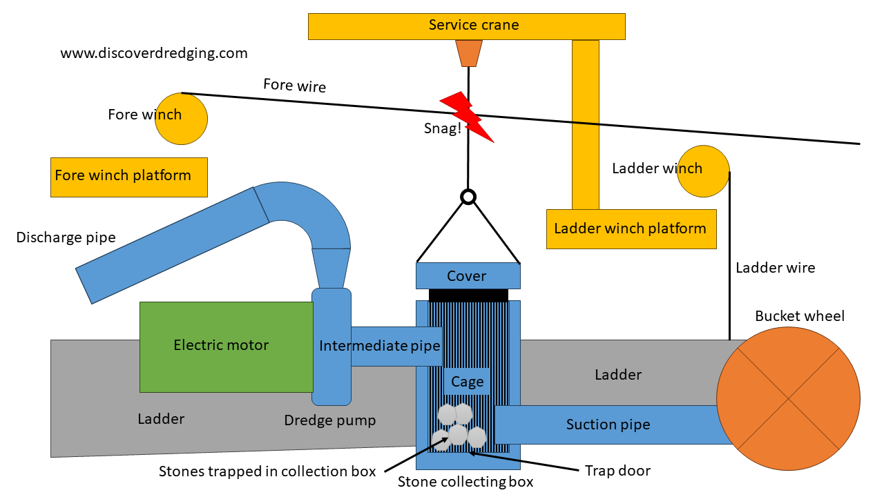
The thing is, when you have anything in the suction pipe section, it will create a pressure loss and the pressure in front of the dredge pump becomes lower. Or higher vacuum, as you wish. This is already a problem for an inboard pump when you are working at sea level, even more so when working at altitude. The NPSHr is easily reached. In order to have enough NPSHa, even when the stone collecting box was filling up, it was decided to have a submerged dredge pump for increasing the pre-pressure. Consequently, the stone collecting box would also be placed on the ladder, in front of the dredge pump.

Explanation on NPSHr and NPSHa in mountains and submerged, including stone box

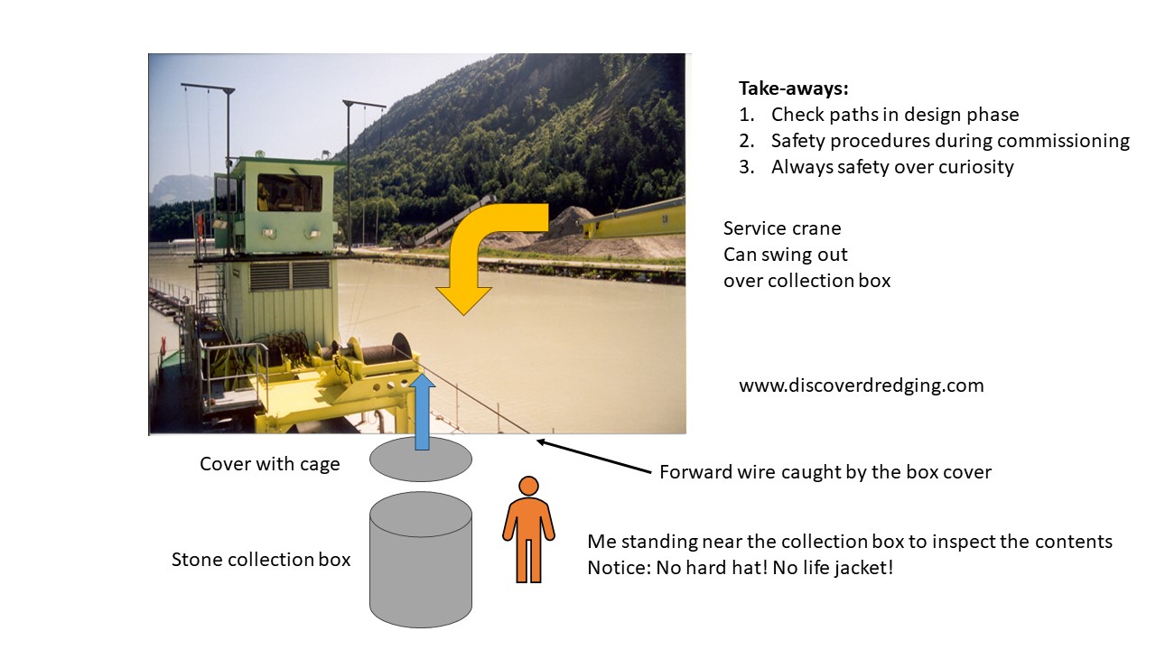
All in itself no problem. The disadvantage is that a submerged stone collecting box should be very strong, big and heavy to withstand the under pressure, although there is very little room around the ladder, the ladder itself becomes quite heavy and bulky and the submerged frontal area increased dramatically, increasing the total drag of the dredge in the fast flowing river current. To mitigate this, the ladder winch, the service crane and the 25 ton forward wire winch were all stacked over each other, so each could do it’s job independently. Although none of us ever did a collision check in the design phase of the dredge. In actual operation, they all were in each others way. When lifting the cover of the stone collecting box, it got caught by the forward wire. When lifting it further, it slipped of the side by the strong drag forces on the wire. I was to first to experience our negligence and got hit on my head when I was to eager to inspect the contents of the box. I blacked out, fell in the frigid water in the ladder well and woke up washed up on the ladder. My colleagues rushed me to the hospital, where I ended up between all sorts of winter sports injuries. Fortunately for me, I am able to recount my story and share it here and through the CEDA Industry News.

Annotated overview of the accident site where the wire slipped from the cover onto my head.

References

  1. Dredging safety under the spotlight, CEDA
  2. Safety is paramount, CEDA
  3. Welcome to CEDA’s (revamped) Dredging Days 2024
  4. The Dredge That Refused to Work on Monday Morning
  5. A Reservoir of Dredging Opportunities

See also

Sunken Treasures From ¡VAMOS! At Silvermines

Overview of the ¡VAMOS! test operation in the Magcobar Pit, Silvermines, Ireland

Last week, I was at a test site for the ¡VAMOS! project. It was in the abandoned Magcobar Pit1. Well, only in ancient times, people have been digging for silver at this location. In 1963 the site was opened for a large scale operation to mine Baryte2. A mineral used in the oil industry. After the veins ran out in the open cast mine, they continued underground, extending the tunnels almost to the next mine in an adjacent area. Then they had to stop operation altogether and the pit got filled with water from a small river that now enters in an attractive waterfall. So far the historic perspective of this site. Currently the forgotten mine is bustling with activity. So many people and equipment was brought in from all corners from Europe, it looked like a circus has come to town.

The ¡VAMOS! road show on its way to Silvermines, Ireland

When I came there, the team had already set up camp and assembled the Launch and Recovery Vessel. The Mining Vehicle was ready to be deployed and we could commission and test the special drive we had provided for the project3. Another item we had to commission was the dewatering facility. Well, it is a fancy name for a dump area. Basically, it is a reclamation area, where we can collect the material that has been cut by the mining vehicle and was pumped through the discharge line to the shore. We had one pond for collecting the cuttings and one pond for containing the fines. Eventually all effluent water was skimmed trough an overflow box.

Overview of the dewatering facility

As there might still be some very fine material contained in the overflow water, we wanted to dispose the water at a lower level than where we were going to do the cutting tests with the mining vehicle. This would ensure clear visibility and an undisturbed background turbidity for the effects measurements. A submerged pipe line for dredging is a well-known component in the dredging industry. If e.g. a discharge line of a cutter suction dredge has to cross a busy fairway, the discharge line is submerged under water, so the traffic can pass without interruption.

Example layout of a submerged dredge line

There are several issues to pay attention to. Selecting the right diameter is the first to consider. You definitely don’t want to block the submerged dredge line. In order to reduce the critical velocity and increase the mixture velocity, the diameter of the submerged pipe is usually chosen a bit smaller than the rest of the pipe. Furthermore, you don’t want any air get trapped in the submerged line. Air inside the line will make the pipes float again, usually at the most inconvenient moment and probably damage the line. Positioning the submerged line can be done by actually having the air in the line slowly escape. The line will lose buoyancy and settle on the bottom. Injecting compressed air will float the line again.

Deployment of a submerged dredge line

The mining we are doing at the Magcobar Pit is solely for scientific purposes. The material we gather and sample will not be used. But, we hope our technology will revive some disused mines again to their former glory. At least get some people back at work. There are a lot of little villages that fully depended on the activity of the mine. The little town of Silvermines is still remembering those good old times with a little monument to commemorate a glorious past4.

Memorial for the mining industry in the town of Silvermines

References

  1. ¡VAMOS! preparing for second field tests in Ireland, ¡VAMOS!
  2. Baryte, Wikipedia
  3. Dual Stage Dredge Pump and Double Action Pump Drive for ¡VAMOS!, Discover Dredging
  4. Silvermines, Wikipedia

See also

Perspective on Commissioning – Connecting the DOP’s

DOP pump and power pack, ready for commissioning

A DOP pump1 and it’s drive go together like a horse and carriage, you can’t have one without the other. Basically one product, but two units. Whether hydraulic or electric driven. OK, in some cases, you could use the extra power take off from the excavator or crane, but you still have to hook them up, before they can do any useful work.

And connecting the DOP to its drive is an elementary job, that can cause some headaches, when not done carefully. The modern electric drives require some more certified wizardry, that is beyond the scope of this post. Hydraulic power packs have their own peculiar quirks, that are worth mentioning here.

Usually, the hydraulic hoses come supplied with Snap-tite® connections2. These are quick and prevent most oil spills in the environment. They come with a disadvantage in price and resistance. Ultimately, the DOP should be connected to the power pack like this:

Hydraulic diagram DOP pump and power pack

So, even with such a simple diagram, still things can go horribly wrong. Off course, don’t switch the ‘Pump’ and ‘Return’ line, you will blow some seals on the motor. Most common is a failed connection of the Snap-tite®. When it is not completely tight, the internal valve is not completely open and you have a lot of resistance. So a lot of power on the power pack gets converted to heat on the connection and no performance on the DOP pump. Another common problem is the resistance in the leak line. This can cause terrible things on the hydraulic motor.

One client followed all the instructions in the manual and all advise from the service department, but still could not coach his new DOP to work. Lots of flow at the power pack, but almost no pressure. And the impeller could still be turned by hand. (Warning: never put your hand in an impeller when there is power on the drive!) One of our engineers went over to have a look on board. Well, here is an impression of the situation on deck.

Situation on board during commissioning

He quickly began cleaning up the mess on deck and uncovered how the hydraulic hoses were actually connected.

How the DOP pump was connected (not), actually

Well, that makes sense! Now it was easy to see, why the DOP was not working. Solution, connect the lines correctly and dredge away. Oh, and educate the crew about a tidy workplace.

Ship shape and ready to rumble

Well, after this first basic lesson in connecting the DOP, you are ready to connect your own DOP project. It’s easy as child’s play.

Connect the dots to set up a DOP project yourself (pdf version)

References

  1. Hydraulically driven submersible dredge pump DOP, Damen
  2. Quick Disconnect and Valve Division, Parker Snap-tite

See also