Super Materials To Improve Lifetime When Your Pump Is On Acid

Severely corroded impeller next to the original wear part

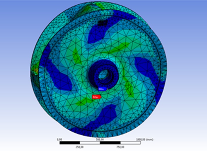
Recently I had a discussion on LinkedIn about the pump killer #2: ‘wrong material’. There I chipped in with this disaster picture1. It was an application where we provided a suboptimal material for the acid environment. The consequences were disastrous, as seen above. Luckily, we were able to identify the problem and propose a different material. Now, I want to share our experience here, also.

What was the case? A client requested a DOP for handling tailings in their facility. Tailings is fine stuff. Leftover from mining or waste water processing. We are always careful on the grain size, as these fines may interfere with the operation of the mechanical seal. With appropriate measures, they can handle them. As the grains tend to be fresh, they can be razor sharp. The erosion on the wear parts is higher than normal fine silt. Oh, and most tailings come with acid in their water.

So, for this request we proposed a material that was usually good in wear resistance and had a moderate resistance against corrosion. Casting materials can be classified for their corrosion resistance with the Pitting Resistance Equivalent Number2. This PREN can be calculated with:

PREN = Cr + 3.3Mo + 16N

Two observations to this formula. One, this is only valid for normal Chromium content materials intended as Stainless Steel. Two, it does not mention the aggression of the corrosion. The acidity is usually provided in the request for quotation. But, a catalyst for the oxidising reaction is the conductivity of the fluid. Chloric acid and sulphuric acid may have the same pH, but due to their different ion and electron content, their conductivity differ. We did not check this in the above example, with the consequences in the picture.

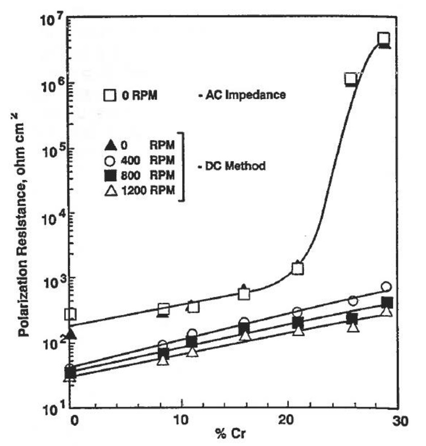
Is increasing the chromium content in the wear alloy a solution to this corrosion problem? Mwah, moderately. Alloys like stainless steel profit from the above approach. But, wear materials use their Chromium for generating carbides. Those are the particles we require for the wear resistance. The Chromium provided is than not available for corrosion resistance. e.g. White cast iron with 3%C and 21%Cr will only have about 6% of Chromium to be used in the PREN. For white cast irons, it is better to use the following graph3 to find their corrosion resistance.

Corrosion Properties of Cast Iron Ball Materials in Wet Grinding. (Credit: Corrosion Feb 1992)

If corrosion is such an issue, why don’t we use Stainless Steel? Well, there you bite yourself in the tail. Stainless Steel in itself is relatively soft. It would have the same wear index of normal construction steel. By definition a Wear Rate Index of 1. For the sharp tailing material, that would be disastrous in itself. But, let’s play along. The stainless steel derives it’s corrosion resistance from the Chromium as explained before. Chromium’s trick is to generate a clear closed patina layer of Chromium Oxide protecting the underlaying material. In dredging conditions, the particles damage the protecting patina forever exposing fresh base material for more erosion and corrosion. In the end, the wear is accelerated and part life decreases dramatically.

Accelerated erosion process under corrosive conditions

Back to the pictured example, we expected some corrosion, but did not expect the higher conductivity. So, after three weeks, the client noticed a sudden los of performance. The leading edge of blades and the hub shroud were completely eaten away. As long as the trailing edge was there, it generated head. A single stone hit severed the front of the impeller from the hub and we received the above disaster picture. After damage evaluation, we sent a CW250 impeller and that one lasted.

A corrosion resistant DOP working in an acid tailings pit

References

  1. Pump killers: How to fight the 13 most common centrifugal pump failures? Number 2., Jos Overschie
  2. Pitting resistance equivalent number, Wikipedia
  3. Corrosion Properties of Cast Iron Ball Materials in Wet Grinding, Corrosion

See also

Graduation Of Carsten Markus: Designing And Casting Of Impellers

Impeller under operating load.

Last week, Carsten Markus graduated on his assignment with our research department Damen Dredging Equipment. He investigated the alloys that are used to cast our impellers and the responses of the materials under operating conditions. We are always improving our dredge pumps and Carsten’s work has been a great contribution for our development.

For every dredging application, the material for the dredge pump parts can be carefully selected according the specific requirements on the sediment handled. Off course, one would like to have the hardest, most erosion resistant material available. Less erosion is less wear and a longer lifetime1.

Wear part material hardness in relation to wear index

However, there is a downside to choosing very hard material: it will be very brittle also2. Basically, the ultimate tensile stress coincides with the yield stress. There is no reserve for the load. When the stress surpasses the yield strength, it just snaps. Conversely, a tough material has a lot of reserve. After deformation beyond the yield stress, the load can still increase without a catastrophic failure. Usually, the stresses would not be that high, the thickness of the wear parts is dimensioned for erosion reserves and thick parts have low stresses. The high stresses can come from concentrations. Either when the wear reserves are eroded, or when a heavy load is concentrated on a very small area. Usually stones. Stones are a very common problem in a dredging project. So, next to the hardness of an alloy, also the toughness will be a very important characteristic. And toughness is related to the yield elongation after failure.

For the various materials you would like to know how the base load relates to the tensile stress. This would be an indication whether there is reserve in the elastic region to accommodate the impact of an occasional stone. This base load depends on many factors in the pumping process. Mainly the pressure generation in the mixture over the blades. Most known literature is about the force distribution in the volute of the pump, as this is directly related to the radial forces and consequently the bearing and shaft calculations. The CFD simulations in this graduation project revealed the skewed load on the volute and consequently the load variations on the impeller.

Transient CFD simulation of a dredge pump. The rotation appears wrong , but is correct (Wagon-wheel effect).

As emphasised before, it is very beneficial to operate your dredge system around the Best Efficiency Point (BEP). Not only the shaft and bearings suffer less, also the impact of the stresses and their variations in the impeller are less. If the operating point differs from the required capacity, the BEP can be moved by changing the dredge pump speed. As long as head requirements permit the adjustment.

Radial load as a function of pump characteristics.

As a result of Carsten’s research, we were able to improve our operating load models for the whole dredge pump and gained insight into the material responses to these. Thank you Carsten.

Due to the measures taken for the containment of the Corona virus, the graduation itself and the party to celebrate it, where done remotely over internet. Let’s enjoy the real beer later, after all this commotion is over. Stay home, stay safe.

Carsten’s graduation defence session under Covid-19 measures.

References

  1. Do You Have Wear Parts For Spare?, Discover Dredging
  2. Brittleness, Wikipedia

See also

Which Teeth Will Survive The Cut? Adapting Your Selection

Me, explaining about our cutter systems

After my last post1, I received some comments and questions about the actual products we are applying in our cutter systems for our CSD’s2. Indeed, from a pure physical perspective, last post cuts to the heart of the processes, but does not explain our design of the working tool that makes a cutter suction dredge do its work.

Over the years, there has been a lot of development in this tool. Originally, suction dredges were plain suction dredges, working in non-cohesive sand. When the soil was more cohesive than could be dug with the standard suction dredges, attaching a mechanical device for loosening the ground enabled the suction dredge to work in this environment. From this original concept, the cutter head was already recognisable as a crown with teeth on a back ring and a suction mouth in the centre. From there, a lot of experimentation was done, but ultimately it all came back to this concept. Although modern cutter heads have a vastly improved performance and lifetime.

The cutting process in a modern cutter head is a combination of the rotation of the head and the swing of the dredge. The teeth describe a compound path of translation and rotation and each individual tooth has its own set of cutting parameters for depth and angle varying over time. Moreover, the combination of teeth on the different arms, allow for a staggering of the teeth that each tooth cuts fresh material and optimising the use of the teeth and spreading the wear. This results in a complicated geometry of the arms and a intricate pattern of the teeth.

Teeth system with adapters (left) teeth system direct on arm (right)

Once a cutter design has been chosen, there is still some tuning possible. Normally, the teeth are fitted on adapters and there are several teeth types available for a certain adapter. Pick points, Chisels and Flares. Most productivity can be expected from the wider teeth. However, the penetration of the wide teeth is less. So, for harder material you want to select narrower teeth.

Adapter system (left), teeth range with adapter (top), teeth range direct on arm (bottom)

Wear is also an issue3. And as the teeth are in direct contact with the fresh material, the wear rates can be severe. The disadvantage of a teeth and adapter system is that that are quite big. So, less teeth fit on an arm, reducing production on average. As most of our CSD’s are working in more gentle sands we selected a cutter system, that provides more teeth to engage in the action, increasing production. As these teeth are fitted directly on the arms, there are no adapters that wear also. Consequently having no adapters, simpler arms and dirt cheap teeth result in a low investment low OPEX cutter system. Although you might have to check the state of your teeth more often, in the end you spend less money on a cubic meter produced.

Teeth in various stages of degradation

Teeth can be worn down to the root. Also they are not wearing evenly. Usually, they last longer on the outside, near the back ring. You might consider using different tooth forms over the arm. Experience and practice, will guide you in selecting the best combination. In line with the previous post, the analogy will be on the table. Just as you select different teeth for your fork, you can select different teeth on your cutter depending on the dish being served.

Different teeth selection for tableware

References

  1. Experiencing The Cutting Edge Of Dredging Technology, Discover Dredging
  2. Cutter Suction Dredger, Damen
  3. Wear of Rock Cutting Tools, Peter Verhoef

See also