Modern Uses And Legendary Excuses For Manual Depth Sounding

Depth sounding lead and rope

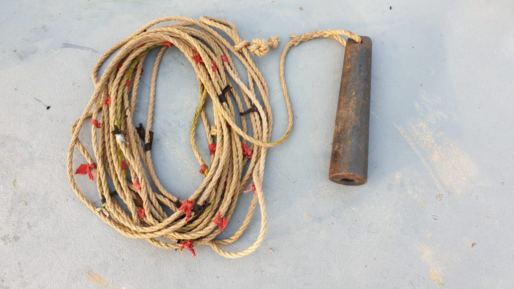
Never waste a moment to tell a good story. Usually, you’ll find informative or educational stories on this platform. This time, I literally found an opportunity to tell you a fun story. All it took, was this nifty little classic navigational instrument. The crew on the dredge used to calibrate their modern survey system1 or checked the delivered depth with this ancient tool. Ever seen one like this? It is a depth sounding lead2. Well, I doubt this one was made from lead, based on the estimated weight and appearance, but it does have all the other characteristics of a normal depth sounding lead.

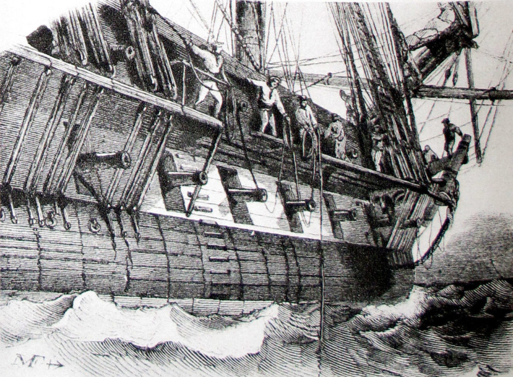
Evolving from a stone on a rope, the depth sounding lead was used to sound the depth. The plummet was made from lead. The rope was marked at regular intervals according to the shoe size of the current king. Cast overboard, the lead sank and keeping the rope tight, the depth at that location could be read from the markings on the vertical rope. It involved some nimble dexterity to stand at the lee side of a fast moving vessel in a choppy sea to handle the lead, a bundle of coiling rope and accurately reading the depth at the right moment. Hands down to all those seafarers that explored the world in old times and managed to navigate the globe on this instrument.

Sounding the depth manually with rope and lead (Credit: Wikipedia)

The depth was not the only information gained from this action. When you look closely, there is a hole at the bottom of the lead. On the picture above it is empty, but it ought to be filled with grease or wax. When the lead touched the bottom, some of the dirt was caught in the grease. When the lead was retrieved, the cling-ons were inspected. These could be either: sand, mud, gravel, peat, silt or even shells and other biological detritus. The material was reported on the charts also. This made navigation in charted waters easy: compare the sample with the indicated bottom condition. And that brings me to my fun story.

Before the Dutch reclaimed their land, there was a large water body in the Netherlands, called the ‘Zuiderzee’3. Or, South Sea as opposed to the North Sea, which most of you might know. This Zuiderzee, was extensively used for fishing. The skippers did not have charts, but they relied on oral tradition handed down through the ages of where what kind of soil would be available. Near Urk, you might find rocks. Near Pampus, there will be a lot of mud and around Stavoren, there is the famous ‘Vrouwenzand’ (Sand Bank of the Lady of Stavoren4). So, when the fishermen cast their depth sounding leads out, they knew the location of their vessel and the depth beneath it.

Map of the ‘Zuiderzee’ (Credit: Wikipedia)

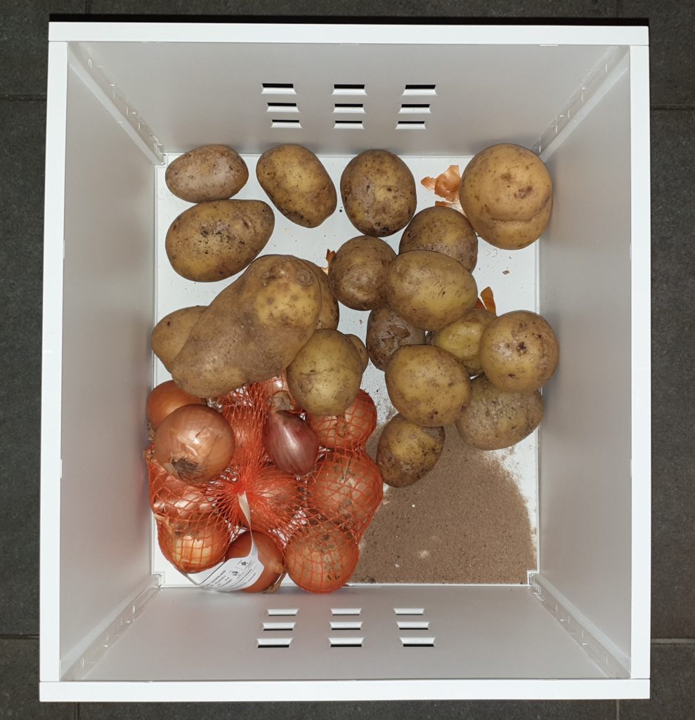
One of those skippers boasted he did not even have to see and feel the sample, but just by tasting it, he could pinpoint his location within a hundred yards. Hard to believe, right? The cabin boy on board thought likewise. So, he devised a cunning plan. After lunch, the skipper went down to the cabin for a short nap and instructed the cabin boy to bring him the lead to taste the sample. But, our clever cabin boy sank the lead in the crate with potato’s. The bottom of the crate was covered with clay from the potato’s. Carefully bringing the sample to the skipper, the cabin boy woke him up and awaited his reaction. The skipper woke up groggily and grappled for the lead with half closed eyes. He stuck his finger in the sample hole and tasted the material inside. Suddenly, his eyes went wide open and he exclaimed: Oh, disaster! The dikes have broken again! The land is flooded and we are sailing over farmer John’s potato patch!

You never know what you dredge from the bottom of a potato crate

References

  1. Positioning and survey system, Damen
  2. Depth sounding, Wikipedia
  3. Zuiderzee, Wikipedia
  4. Lady of Stavoren

See also

CEDA DMC Works On A Guidance Paper For Soil Investigation

CEDA Dredging Management Commission WG on Soil Investigation (Credit: CEDA)

Did you ever start a project and it turned out that the conditions were different than expected? Welcome to the dredging industry. One of the most underestimated preparations for a dredging project is the soil investigation. As this investigation is of the utmost importance for the dredging community, the DMC is preparing a guidance paper on this topic1, which we discussed last meeting (February 7, 2020, IMDC, Antwerp).

Working for a dredging equipment manufacturer, I am not much involved in the actual soil investigation. However, often our clients base their purchase of a specific type of equipment on the soil investigation and as such we are often presented with the reports on soil investigation. Based on these reports, we calculate the possible production for various types and advise the client for a dredge that will meet their requirements on the maximum production. most of the time we provide a good advise and the client is happy.

Off course there have been occasions where the performance was not as expected. Often because the report on the soil investigation was inadequate. Either the report did not contain all the details, or the investigation itself was lousy. Either way, rubbish in, is rubbish out. Just as an example, let me tell you what can go wrong, when the information is not representing the real circumstances.

One of our products are the so called ‘DOP Dredges’2. They are based around the versatile DOP pump. Basically, it a DOP suspended on an A-frame on a pontoon with a powerpack. The DOP can be lowered into the sediment and create a typical suction dredge pit. The production is more based on the rate that water can enter the bank face and the velocity that the banks recede. Our client provided us a Particle Distribution Diagram of the available sediment3. It was a nice narrow graded sand, but there was a considerable fines tail on the lower end. This was being dealt by the washing and screening installation. According to the client was this the sand characteristic from the whole pit. And what could be better? If you excavate all the material, you really know what is there, right?

Difference between expected soil conditions (left) and real situation (right)

Well no. As it happened, there were cohesive silt layers between the narrow graded sand layers. When dredging, they sucked at the bottom of the pit. Any silt layers gradually broke of and disintegrated by the eroding density flow. As the pit was created over a long period, the falling chunks of silt just slid down the slope, without causing any harm.

Enter: the new DOP dredge. It started in a new corner of the pit and initially had some trouble penetrating the silt layer. Eventually it managed to get through and started excavating a cavity below the silt layer. These broke of, burying the DOP. Without any possibility to recover the DOP, it turned into a very expensive anchor.

Risk of getting your DOP trapped in a cavity under the cohesive silt layers and the solution

If the presence of these cohesive silt layers would have been known, we would have adapted the suction pipe for a deeper penetration. That prevents the DOP becoming covered and facilitates easier extraction. This story proves two things: 1. A proper soil investigation can prevent costly accidents and budget runovers. 2. A DOP can be modified to most requirements, when the circumstances are known.

Meanwhile, the DMC is preparing its guidance document to assist you in preventing problems like this. Follow CEDA for updates4.

Standard suction tube (left) and long suction tube (right)

References

  1. Dredging Management Commission, CEDA
  2. DOP Dredger, Damen
  3. A Sample of Soil Samples, Discover Dredging
  4. News, CEDA

See also

Painted Hills, how to unveil the sediment layers below the surface

Painted Hills, Oregon, USA

Last year we had an extended holiday. We wanted to observe the solar eclipse, but we took the opportunity to sail and drive across the United States. Sure, the eclipse was certainly one of the most impressive events. But the above picture was haunting my mind throughout my vacation. Is it familiar to anyone? Is there anyone an avid follower of ‘Who is the Mole’? Yes, these are the Painted Hills. In season 17 part 8, this is where Sanne Wallis de Vries mixed up the alphabet and Diederik Jekel had to leave the show. As our plans were already to visit the state of Oregon, we decided to see the location. Most striking are the coloured bands of sediment. Each colour represents a different geological age. After erosion, the layers became exposed. Usually, these sediment layers are covered and submerged, invisible to the dredge contractor or operator.

Nothing to see here

However, these layers can be made visible by performing a soil investigation. The bottom is probed with a Cone Penetration Test or CPT. It measures two parameters: the undrained shear strength and the cohesion. The shear strength can be measured by pushing a cone through the soil. The cohesion by pulling a sleeve through the hole the cone just created. This way the parameters are uncoupled. Imagine being able to identify the resistance of a hull separated in form friction and skin friction!

Sometimes also other measurements can be performed on the same sensor: water pressure, acidity, conductivity, light reflection; all attributing to a better understanding of what is beneath the surface.

Infographic on CPT

The values for shear strength, cohesion and optional other parameters can be plotted in the same diagram against the penetration depth. Correlating the parameters can reveal what type of layers are there. Very easily clay and sand can be identified. Also gravel layers are recognised. Stones and debris are sometimes hidden as soundings that were aborted. Keep an eye out for signs like these, as they have a major impact on your project. The more soundings available, the better the project estimation. There is a PIANC guideline for the number of soundings for the area1. Anything less is meaningless.

Example of a sounding diagram

A soil investigation report comprises a number of these diagrams and possibly also core samples for establishing a particle size diagram. If the client attaches such a thorough soil investigation report, we can work on it to select the best dredging equipment for the project and advise on an optimal working method.
The data of the Cone Penetration Tests can be used also as input for survey programs like Navguard. e.g. If a certain layer has to be removed, the depth of that layer can be presented to the operator as the design depth. So, NavGuard can be an excellent tool to dredge exactly what is needed, without extra work and costs. Certainly an option that will pay back quickly.

Screenshot of NavGuard survey program

References

  1. PIANC, Site investigation requirements for dredging works

See also